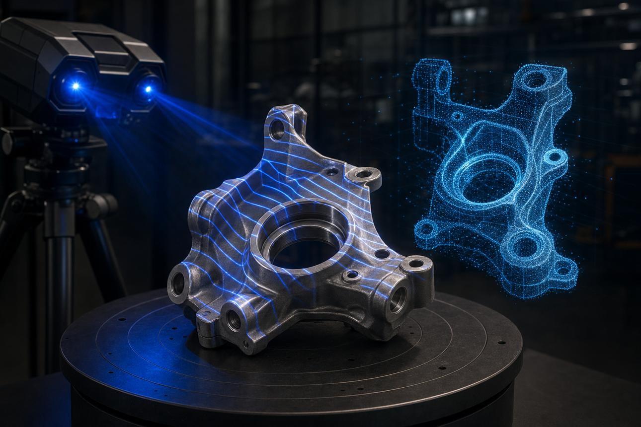
Is Designing From Scratch Always Faster?
In precision manufacturing, time-to-market is one of the biggest challenges facing engineering teams.
When a new component, replacement part, or tooling project comes up, engineers often assume that creating a completely new CAD design will be faster and more efficient than reverse engineering an existing physical part.
That assumption is not always correct.
In many real-world manufacturing environments, the physical part already contains valuable engineering information: its dimensions, interfaces, freeform surfaces, mounting locations, clearances, and actual geometry. Starting from zero means recreating much of that information manually through measurement, calculation, assumptions, and multiple design iterations.
By contrast, 3D scanning and reverse engineering can turn an existing physical component into usable digital engineering data, providing a faster starting point for CAD reconstruction, inspection, redesign, tooling, and manufacturing.
Modern 3D scanning technologies are widely used for reverse engineering because they can capture complex physical geometry as point clouds or meshes, which can then be reconstructed into CAD models.
So when does reverse engineering actually make more sense than designing from scratch?
Here are five manufacturing situations where 3D scanning and reverse engineering can significantly accelerate engineering work.
What Is Reverse Engineering and Why Is It Often Considered “Slow”?
Reverse Engineering (RE) is the process of measuring an existing physical object and reconstructing its geometry and design intent as a digital model.
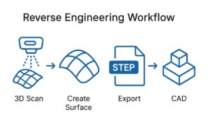
In a manufacturing workflow, this commonly means:
Physical Part → 3D Scan → Point Cloud → Mesh → Surface Reconstruction → CAD Model → Engineering Modification → Manufacturing
The goal is not simply to create a visual copy.
A professional reverse engineering process aims to recover usable engineering information, including:
- Critical dimensions
- Geometric features
- Freeform surfaces
- Mounting interfaces
- Datums and reference geometry
- Clearances and fitment
- Design intent
- Manufacturing requirements
This distinction is important.
Traditional reverse engineering may involve manually measuring individual features with calipers, gauges, or other measurement equipment and then recreating the geometry in CAD. For complex components, that approach can become time-consuming and prone to missing information.
Industrial 3D scanning changes the workflow by capturing large amounts of surface geometry digitally. Depending on the scanner and application, technologies can include handheld laser scanners, structured-light scanners, and other optical measurement systems. Creaform, for example, describes 3D scanning as a common approach for extracting dimensional information for reverse engineering and generating point clouds or meshes.
The important point is this:
3D scanning does not replace engineering. It gives engineers a much better starting point.
The scan data still needs to be cleaned, aligned, interpreted, and converted into an appropriate CAD representation.
5 Situations Where Reverse Engineering Can Be Faster Than New Design
1. The Original CAD Drawing or Model Is Lost
One of the most common reverse engineering scenarios occurs when a physical component exists but its original engineering documentation no longer does.
Consider a machine component manufactured 10 or 20 years ago.
The equipment may still be operating, but:
- The original CAD file is missing
- Engineering drawings are unavailable
- The original supplier no longer exists
- The component has been discontinued
- Documentation is incomplete
- The machine was imported without complete technical records
Designing the component again from scratch means determining its geometry, interfaces, dimensions, and critical features manually.
For simple parts, this may be manageable.
For complex components with curved surfaces, multiple interfaces, or tight fitment requirements, it can become a much larger engineering task.
A 3D scanning approach
A typical workflow is:
Physical Component → 3D Scan → Point Cloud → Mesh → CAD Reconstruction
The scan captures the actual geometry of the existing component, providing engineers with a comprehensive digital reference.
From there, the engineering team can reconstruct the part as a surface or solid/parametric CAD model depending on the intended application.
The result is not merely a digital archive. It can become a new engineering asset for:
- Replacement manufacturing
- Design modification
- Tooling development
- Simulation
- CNC programming
- Quality inspection
This is one of the core applications of industrial 3D scanning and reverse engineering.
Best fit: Legacy machinery, discontinued components, imported equipment, obsolete parts, and undocumented assemblies.
2. A Part Is Worn, Damaged, or Deformed
Reverse engineering becomes particularly valuable when the original geometry is difficult to determine because the physical component is no longer in its original condition.
Examples include:
- Worn shafts
- Damaged housings
- Deformed brackets
- Heat-deformed components
- Damaged tooling
- Worn mechanical interfaces
Designing from scratch creates a difficult question:
What was the original geometry supposed to be?
A damaged component may no longer represent the intended design accurately.
3D scanning provides a digital record of the actual physical condition. Engineers can then combine the scan with engineering knowledge, symmetry, reference features, mating components, or an undamaged counterpart to reconstruct the intended geometry.
For example, if one side of a component remains intact while another side is damaged, the intact geometry can provide a reference for reconstruction.
This approach can be considerably more reliable than estimating the original geometry visually.
The final CAD model can then be used for manufacturing a replacement component or for further engineering analysis.
3. You Want to Improve an Existing Product Without Starting Over
Not every engineering project is about creating something completely new.
Often, a manufacturer already has a product that works well but wants to:
- Reduce weight
- Improve manufacturability
- Change materials
- Improve ergonomics
- Add new features
- Modify mounting points
- Improve performance
- Adapt the component to a new assembly
Starting a completely new CAD design can mean rebuilding a large amount of geometry that already works.
Reverse engineering provides another option.
Scan the existing product first.
The physical product becomes the baseline geometry.
Engineers can then identify which areas need modification and preserve the features that already work.
This can significantly reduce unnecessary redesign work.
The process can become:
Existing Product → 3D Scan → CAD Reconstruction → Engineering Modification → CAE Validation → Manufacturing
This is especially valuable when the original CAD model is unavailable or when the physical product has been modified over several production generations.
Once the reconstructed CAD model is available, it can also become the foundation for downstream engineering activities.
For example, engineering teams can combine reverse-engineered CAD with CAE simulation to evaluate structural performance before committing to multiple physical prototypes.
This creates a connection between digital capture and engineering validation rather than treating 3D scanning as an isolated measurement activity.
4. You Need Tooling, Jigs, or Fixtures for Complex Freeform Geometry
Freeform surfaces can be extremely difficult to reproduce accurately using conventional manual measurement methods.
This is particularly relevant to:
- Automotive interior components
- Exterior body components
- Plastic housings
- Injection-molded parts
- Composite components
- Custom fixtures
- Assembly jigs
- Tooling
Imagine designing a fixture that must precisely support an existing automotive component with multiple curved surfaces.
Instead of manually measuring dozens or hundreds of points, 3D scanning can capture the overall geometry and provide a digital reference for fixture design.
The engineering team can then design the fixture around the actual part geometry.
This can improve:
- Fitment
- Clearance
- Contact surfaces
- Assembly repeatability
- Tooling development speed
For tooling and fixture applications, however, scan data alone is not enough.
The final CAD model must account for manufacturability, datum strategy, tolerances, machining access, and assembly requirements.
This is where engineering expertise becomes critical.
ASME Y14.5 provides the widely used framework for dimensioning and geometric tolerancing, helping communicate design intent and requirements throughout design, manufacturing, and inspection.
For more complex fixture and manufacturing requirements, dimensional and tolerance information needs to be incorporated into the engineering workflow rather than simply reproducing the scanned surface.
5. A Machine Is Down and the Replacement Part Has a Long Lead Time
This may be one of the most commercially important applications.
Imagine a production line stops because a critical component fails.
The original equipment manufacturer may have:
- Discontinued the part
- Stopped supporting the machine
- A long replacement lead time
- High minimum-order requirements
- Limited documentation
Waiting several weeks for a replacement component may create significant downtime costs.
If a physical component is available, 3D scanning and reverse engineering can provide an alternative path.
A typical emergency workflow
Failed Part → 3D Scan → CAD Reconstruction → Engineering Review → CNC / Additive Manufacturing → Replacement
The physical part becomes the starting point for recreating the digital geometry.
For suitable components, the resulting CAD model can then support CNC machining, additive manufacturing, or other production methods.
The objective is not necessarily to reproduce every feature blindly.
Engineers can also identify:
- Wear areas
- Damaged geometry
- Critical interfaces
- Manufacturing constraints
- Opportunities for improvement
This transforms reverse engineering from a documentation exercise into a downtime-reduction strategy.
New Design vs. Reverse Engineering: A Quick Comparison
| Criteria | New Design | Reverse Engineering + 3D Scanning |
|---|---|---|
| Starting point | Requirements, concept, sketches | Existing physical component |
| Geometry capture | Designed from specifications | Captured from actual geometry |
| Manual measurement | Often significant | Reduced through digital capture |
| Complex freeform geometry | Must be modeled from requirements | Captured directly as scan data |
| Best suited for | New products and concepts | Existing, legacy, damaged, or undocumented parts |
| Design risk | Depends heavily on assumptions and requirements | Grounded in measured physical geometry |
| Downstream use | CAD → CAE → CAM | Scan → CAD → CAE → CAM |
| Main advantage | Full design freedom | Faster access to existing geometry |
The key takeaway is not that reverse engineering is always faster.
New Design is the right approach when there is no existing physical reference or when the product requires fundamentally new engineering.
Reverse Engineering becomes particularly powerful when the physical component already contains most of the geometry you need.
What Makes Reverse Engineering Fast and Effective?
A 3D scanner alone does not guarantee a successful reverse engineering project.
Three factors matter.
1. Choose the Right 3D Scanning Technology
Different parts require different scanning strategies.
Handheld 3D scanners can be useful for larger or complex components where portability and flexibility are important.
Structured-light systems can be advantageous for applications requiring detailed capture of smaller components and complex surfaces.
Large-part applications may require different equipment and scanning strategies again.
Accuracy should therefore be specified based on the actual engineering requirement rather than using one universal accuracy number.
Industrial metrology organizations such as NIST emphasize the importance of measurement science, uncertainty, calibration, and traceability when evaluating dimensional measurement results.
2. Convert Scan Data Into Engineering-Ready CAD
This is where many inexperienced scanning workflows fall short.
A scan usually produces point cloud or mesh data.
A mesh is not automatically a fully editable engineering CAD model.
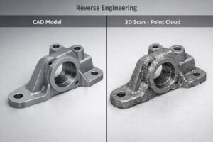
For manufacturing applications, engineers may need to reconstruct:
- Planes
- Cylinders
- Holes
- Fillets
- Datums
- Sections
- Freeform surfaces
- Solid geometry
- Parametric features
The objective is to create a CAD model that engineers can actually modify and manufacture.
That is why the combination of 3D scanning + CAD engineering expertise is much more valuable than scanning alone.
3. Design for Manufacturing Must Remain Part of the Process
A beautiful reconstructed model is not necessarily a manufacturable model.
Before releasing the final CAD data, engineers should consider:
- CNC machining constraints
- Tool access
- Wall thickness
- Draft angles
- Assembly interfaces
- Tolerances
- Material requirements
- Datum strategy
- Inspection requirements
For example, a replacement part may reproduce the scanned geometry perfectly but still fail because the original geometry contains wear that should not be reproduced.
The engineering team therefore needs to distinguish between:
What exists physically and What the final manufactured component should be.
That distinction is fundamental to professional reverse engineering.
From Physical Part to Digital Engineering
The real value of 3D scanning is not the scan itself.
It is what happens after the scan.
A well-designed engineering workflow can look like:
Physical Part
↓
3D Scanning
↓
Point Cloud / Mesh Processing
↓
Surface Reconstruction
↓
Solid / Parametric CAD
↓
Engineering Modification
↓
CAE Validation
↓
CAM / CNC Manufacturing
↓
Quality Inspection
This creates a continuous digital engineering workflow from the physical world to design, analysis, manufacturing, and inspection.
For manufacturers working with automotive components, injection molds, legacy machinery, tooling, and replacement parts, this workflow can significantly reduce the amount of manual measurement and redesign required.
TAS US also provides automotive-focused 3D scanning workflows covering data acquisition, point-cloud processing, mesh generation, CAD reconstruction, reverse engineering, and downstream engineering applications.
For broader manufacturing applications, TAS US supports 3D scanning for automotive components and injection-molding applications, including CAD comparison, reverse engineering, dimensional inspection, and tooling-related workflows.
Final Takeaway: Don’t Redesign What You Can Digitize
Reverse Engineering is sometimes viewed as a fallback option for old or undocumented components.
In modern manufacturing, that view is outdated.
When an existing physical component already contains valuable geometry, 3D scanning can provide a faster and more data-rich starting point than recreating the design from scratch.
It can be especially valuable when:
- Original CAD data is missing
- A legacy component needs to be reproduced
- A damaged part needs to be reconstructed
- An existing product needs modification
- Complex tooling or fixtures need to fit an existing component
- A production machine requires a replacement part quickly
The goal is not simply to copy a part.
The goal is to transform physical geometry into usable engineering intelligence.
At TAS US, our engineering workflow combines 3D scanning, scan data processing, CAD reconstruction, reverse engineering, and downstream engineering support to help manufacturers move from physical components to production-ready digital data.
If you have a legacy component, damaged part, undocumented assembly, tooling challenge, or replacement-part requirement, don’t automatically start the design from zero.
Start by asking: “What engineering information is already contained in the physical part?”
That may be the fastest route to your next CAD model.
Ready to Digitize an Existing Component?
Whether you need 3D scanning, reverse engineering, CAD reconstruction, dimensional inspection, or engineering support, TAS US can help evaluate the most efficient workflow for your application.
Talk to TAS US about your project → Contact TAS US
No responses yet