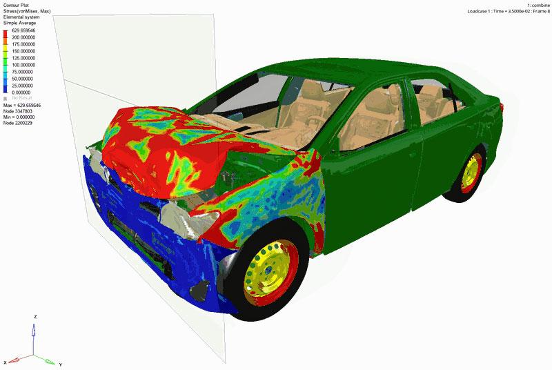
A finite element model can run without solver errors, converge successfully, and produce a stress contour that looks completely reasonable — and still give the wrong engineering answer.
Consider a common engineering situation. An FEA model runs successfully, the stress distribution looks logical, and the predicted deformation appears acceptable. However, after the component is manufactured and physically tested, the real part deforms more than expected or fails in a different location.
The problem may not be the solver.
In many cases, the error comes from how the real engineering problem was translated into the numerical model.
FEA results are only as reliable as the engineering decisions behind the model.
A reliable FEA workflow therefore requires more than creating a mesh and pressing “Solve.” Engineers need to verify the numerical model, validate its physical behavior, and understand how modeling assumptions influence the final result.
Verification vs. Validation: Two Different Questions
One of the most important concepts in simulation engineering is the distinction between verification and validation.
Verification asks: Did we solve the mathematical and numerical problem correctly?
This involves checking the model setup, element formulation, units, mesh, boundary conditions, solver settings, and convergence behavior.
Validation asks: Does the model represent the physical behavior of the real product accurately enough for its intended purpose?
Validation can involve comparison with analytical calculations, benchmark problems, experimental data, or independently validated models.
The ASME Standard for Verification and Validation in Computational Solid Mechanics provides a framework for assessing verification and validation in computational solid mechanics.
This distinction matters because a model can be numerically correct but physically inappropriate.
A solver can converge perfectly while the model still represents the wrong physical problem.
7 Reasons a Correct FEA Model Can Still Produce the Wrong Answer
1. Boundary Conditions Do Not Represent the Real Structure
Boundary conditions determine how a component is supported, constrained, guided, or connected to surrounding structures.
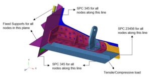
A small change in constraints can significantly change stiffness, reaction forces, deformation, and load paths.
Common mistakes include:
- Applying fixed support to a surface that is not actually fully constrained.
- Locking too many degrees of freedom and artificially stiffening the structure.
- Locking too few degrees of freedom and allowing rigid-body motion.
- Fixing an entire bolt-hole region instead of representing the actual connection.
- Ignoring the compliance of fixtures, brackets, or mounting structures.
Before defining a boundary condition, engineers should ask:
- Where is the component actually supported?
- Is the connection bolted, welded, clamped, pinned, or bonded?
- Can the real component rotate or translate?
- How does the surrounding structure deform?
- Do the reaction forces balance the applied loads?
A boundary condition that is overly idealized can produce a structure that is significantly stiffer than the physical component.
The first check should therefore not be the stress contour.
It should be the physical meaning of the constraint.
2. The Material Name Is Correct — But the Material Behavior Is Wrong
Selecting “Steel,” “Aluminum,” or “ABS” from a material database does not automatically mean that the simulation represents the real component.
Depending on the application, engineers may need to consider:
- Young’s modulus
- Poisson’s ratio
- Yield strength
- Ultimate tensile strength
- Stress-strain curves
- Plasticity
- Temperature dependency
- Anisotropy
- Viscoelasticity
- Strain-rate dependency
- Material orientation
Consider a metal component that experiences plastic deformation.
If the real component exceeds its elastic limit while the simulation uses a linear elastic material model, the FEA model cannot reproduce the subsequent plastic behavior correctly.
The same problem becomes more significant for polymers, rubber, composites, and temperature-dependent materials.
The key principle is: Material data should describe the real part, not merely the material name selected from a database.
The correct question is not simply whether the material was selected correctly.
The better question is: Does the material model reproduce the physical behavior that matters for this analysis?
3. Contact Defines the Load Path
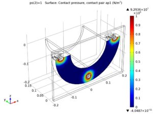
For assemblies, contact can be one of the most influential modeling decisions.
Two components may be modeled as bonded, frictional, frictionless, rough, or no-separation contact. Each assumption produces different mechanical behavior.
For example, using bonded contact between two components that can actually slide or separate may make the assembly considerably stiffer than the real structure.
Common contact issues include:
- Using bonded contact where sliding is possible.
- Ignoring friction.
- Omitting bolt preload.
- Defining incorrect contact surfaces.
- Using overly rigid contact assumptions.
- Failing to inspect penetration.
- Not checking whether contact opens or closes during loading.
The solver may still converge.
The stress contour may still look smooth.
But the load path can be physically wrong.
For this reason, engineers should inspect:
- Contact pressure
- Contact force
- Sliding
- Separation
- Penetration
- Opening and closing behavior
- Load transfer through the assembly
Contact should be treated as a physical representation of how components interact — not simply as a setting required to make the model solve.
4. A Finer Mesh Does Not Automatically Mean a More Accurate Model
One of the most common misconceptions in FEA is:
“A finer mesh always produces a more accurate result.”
A finer mesh cannot fix an incorrect boundary condition, material model, contact definition, or loading assumption.
Mesh refinement is particularly important around:
- Holes
- Fillets and small radii
- Notches
- Geometric transitions
- Contact regions
- Load application areas
- Joints
- Areas with high stress gradients
- Expected failure locations
The more important concept is mesh convergence.
Instead of asking: “How small should the element size be?”
engineers should ask: “Has the quantity of interest become sufficiently stable as the mesh is refined?”
Depending on the analysis, the quantity of interest could be:
- Displacement
- Structural or average stress
- Reaction force
- Strain energy
- Natural frequency
- Contact force
The NAFEMS guidance on mesh convergence highlights why mesh refinement should be evaluated against the quantity being studied rather than simply choosing an arbitrarily small element size.
Another important issue is stress singularity.
At idealized sharp corners, point loads, or perfectly rigid constraints, local stress can continue increasing as the mesh is refined. In such situations, the maximum nodal stress may not represent a meaningful physical design value.
The objective is not to create the finest mesh everywhere.
The objective is to create a mesh that resolves the physics where it matters.
5. The Load Magnitude Is Correct — But the Load Application Is Wrong
A simulation can use the correct force value and still produce an incorrect result if the load is applied unrealistically.
Real-world loads may involve:
- Forces
- Pressure
- Moments
- Acceleration
- Gravity
- Thermal loading
- Bolt preload
- Cyclic loading
- Impact loading
- Time-dependent loading
A point load applied directly to a node can create an unrealistic load path or local stress concentration.
Likewise, applying uniform pressure to a surface that actually receives a nonuniform contact load may produce an unrealistic response.
Engineers should ask:
- How does the real component receive the load?
- Is the load distributed or concentrated?
- Does the loading direction change?
- Is the load static, cyclic, transient, or impact-driven?
- Is preload present?
- Are multiple load cases required?
A quick engineering check is to compare the applied loads with the reaction forces.
Do the reactions balance the external loads?
Then examine the deformation: Does the structure deform in the direction expected from basic mechanics?
Finally: Does the simulated load path match the real structural load path?
These simple checks can reveal major modeling problems before detailed post-processing begins.
6. Solver Convergence Does Not Mean the Model Is Physically Correct
“Converged” is often treated as the final confirmation that a simulation is correct.
It is not.
Solver convergence generally means that the numerical solution has satisfied the selected convergence criteria under the specified formulation and settings.
It does not prove that:
- The boundary conditions are correct.
- The material model is appropriate.
- The contact definition is physically realistic.
- The loading represents the real application.
- The analysis type is appropriate.
This becomes particularly important in nonlinear analysis.
Engineers may need to evaluate:
- Linear vs. nonlinear formulation
- Large deformation
- Material nonlinearity
- Contact nonlinearity
- Load-step size
- Time-step size
- Force, displacement, or energy convergence
- Stabilization
- Damping
For example, a nonlinear contact model may converge with stabilization, while the stabilization itself influences the physical response.
Similarly, in dynamic simulations, timestep and damping assumptions can significantly affect the predicted response.
The correct question is therefore not: “Did the solver converge?”
It is: “Did the model converge to a physically meaningful solution?”
7. Modeling Assumptions Can Become the Largest Source of Error
Every FEA model is a simplification of reality.
The objective is not to eliminate every assumption. That would often make the model unnecessarily expensive and difficult to solve.
The objective is to make sure that each simplification is appropriate for the engineering question.
Typical assumptions include:
- Ignoring small gaps.
- Removing bolts or weld details.
- Using bonded connections.
- Assuming material homogeneity.
- Ignoring friction.
- Applying symmetry.
- Simplifying 3D geometry into shell or beam elements.
- Neglecting thermal effects.
- Treating dynamic loading as static.
- Evaluating only one load case.
The key question is: What could this assumption change in the result?
A useful engineering practice is to document major assumptions and their potential impact.
This makes the analysis easier to review and helps engineers understand where uncertainty may remain.
The NAFEMS guidance on analysis validation also emphasizes the importance of checking the assumptions and decisions underlying an analysis rather than relying solely on the final numerical result.
A Practical FEA Verification Checklist
A reliable FEA workflow can be divided into three stages.
Before Solving
- Define the engineering question.
- Identify the required output quantities.
- Review the CAD geometry.
- Check units.
- Verify material properties.
- Select the appropriate material model.
- Define realistic boundary conditions.
- Define contact behavior.
- Review load cases.
- Select appropriate element types.
- Establish a meshing strategy.
- Document major assumptions.
During Solving
- Monitor solver warnings and errors.
- Check rigid-body motion.
- Review convergence behavior.
- Monitor contact status.
- Check load-step or timestep behavior.
- Review relevant energy terms.
- Investigate unusual numerical behavior.
After Solving
- Check reaction-force equilibrium.
- Review the deformation shape.
- Check the load path.
- Perform mesh convergence.
- Compare with analytical calculations or simplified models.
- Perform sensitivity studies.
- Compare with experimental data when available.
- Confirm that the result answers the original engineering question.
A simulation should therefore not be considered reliable simply because the solver completed successfully.
It should pass a chain of engineering checks covering numerical behavior, physical consistency, sensitivity, and validation.
From “The Model Runs” to “The Result Can Be Trusted”
A credible FEA process can be represented as:
Physical Problem → Idealization → Material Model → Boundary Conditions → Loading → Contact → Mesh → Solver → Verification → Validation → Engineering Decision
If one of these links is based on an inappropriate assumption, the final result may be misleading even when the solver produces a clean solution.
This is why experienced CAE engineers do not evaluate a simulation only by looking at colorful contour plots.
They ask:
- Does the model represent the real structure?
- Is the load path physically correct?
- Are the assumptions appropriate?
- Has mesh sensitivity been investigated?
- Does the result agree with analytical or experimental evidence?
- What uncertainty remains?
The objective of FEA is not to produce a colorful result.
The objective is to produce engineering information that can support a technical decision.
CAE Simulation Support from TAS Vietnam

TAS Vietnam’s CAE simulation services support engineering and manufacturing applications involving structural analysis, dynamic analysis, vibration and NVH, fatigue, thermal analysis, crash-related simulation, and design optimization.
The workflow can include model preparation, material and element selection, boundary-condition setup, loading and contact definition, simulation, result interpretation, and engineering recommendations.
TAS Vietnam also combines CAD and CAE engineering capabilities with manufacturing-oriented engineering services, helping connect simulation results with product design and production considerations.
For engineering teams facing unexpected deformation, stress concentrations, mesh sensitivity, or differences between simulation and physical testing, reviewing the assumptions behind the model can be more valuable than simply changing solver settings.
Need support reviewing or developing an FEA model?
TAS Vietnam can support engineering teams with CAE simulation, FEA model setup, result interpretation, and design optimization for mechanical, automotive, and manufacturing applications.
No responses yet