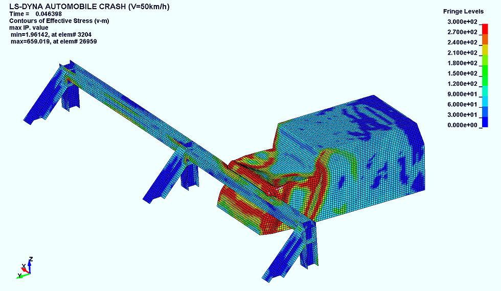
When a moving vehicle hits an obstacle, its kinetic energy drops rapidly within milliseconds. But the energy does not simply disappear.
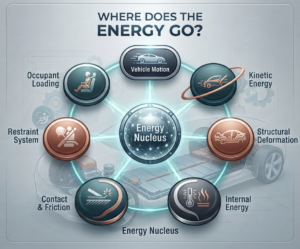
It is transformed and distributed through structural deformation, material plasticity, contact and friction, restraint systems, and ultimately occupant loading.
This is why CAE crash simulation is about more than visualizing how a vehicle deforms. Engineers need to understand where the crash energy goes, how it is absorbed, and whether the numerical model is behaving consistently with the underlying physics.
Energy curves such as Kinetic Energy, Internal Energy, Contact Energy, and Hourglass Energy provide important information for evaluating both structural performance and model quality.
From Vehicle Motion to Occupant Loading
A simplified crash energy flow can be represented as:
Vehicle Motion
      ↓
Kinetic Energy
      ↓
Structural Deformation
      ↓
Internal Energy
      ↓
Contact & Friction
      ↓
Restraint System
      ↓
Occupant Loading
These mechanisms do not occur independently or in a perfectly sequential order. They interact throughout the crash event.
For CAE engineers, the key is to understand the complete energy balance, rather than relying only on deformation contours or stress results.
1. Kinetic Energy: The Initial Energy Budget
The kinetic energy of a moving vehicle is:
KE = ½mv²
where:
- m = vehicle mass
- v = vehicle velocity
- KE = kinetic energy
The important factor is the squared velocity.
If vehicle mass remains constant, doubling the velocity increases kinetic energy by approximately four times.
For example, a 1,500 kg vehicle has approximately:
- 145 kJ at 50 km/h
- 579 kJ at 100 km/h
This illustrates why relatively small changes in impact speed can significantly change the energy absorption requirements of a vehicle structure.
For a crash simulation, engineers therefore need to correctly define:
- Vehicle mass
- Initial velocity
- Mass distribution
- Initial conditions
- Boundary conditions
- Contact definitions
If the initial mass or velocity is incorrect, the entire energy balance of the simulation can be affected.
Kinetic energy is essentially the initial energy budget that the vehicle structure and safety systems must manage.
2. Controlled Deformation: Where Structural Energy Absorption Begins
During a crash, components such as the bumper beam, crash box, longitudinal rails, and subframe can deform to absorb and manage impact energy.
A common misconception is that a safer structure should simply be as rigid as possible.
In crashworthiness design, the objective is more sophisticated.
A well-designed structure should:
- Deform in a controlled sequence
- Absorb energy in predefined areas
- Maintain the integrity of the passenger compartment
- Control load paths
- Limit excessive intrusion into occupant space
For example, a crash box may be designed to progressively collapse during an impact. The deformation is not necessarily a sign of structural failure. It can be an intentional mechanism for energy absorption.
The engineering objective is not simply to prevent deformation, but to control where, when, and how deformation occurs.
This distinction is critical when interpreting CAE crash results.
3. Internal Energy: How the Structure Absorbs Energy
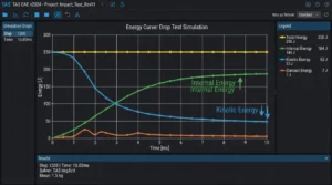
One of the most important outputs in an explicit crash simulation is Internal Energy (IE).
Internal energy represents energy accumulated within the deforming structure through mechanisms such as:
- Elastic deformation
- Plastic deformation
- Bending
- Tension and compression
- Folding and crushing
- Material failure, when included in the material model
For many metallic automotive structures, plastic deformation is a major mechanism for absorbing crash energy.
Therefore, engineers should not ask only: “Did the component survive?”
A more useful question is: “How did the component deform, and how effectively did it absorb energy?”
How should engineers interpret Internal Energy?
An increasing Internal Energy curve generally indicates that the structure is absorbing energy as deformation progresses.
However, the curve should always be evaluated together with deformation and other energy components.
A sudden increase may require investigation of:
- Local structural collapse
- Unexpected folding
- Material failure
- Contact events
- Numerical issues
Conversely, unusually low Internal Energy does not automatically mean that the structure is too stiff. Engineers should also check contact definitions, material behavior, boundary conditions, and deformation modes.
The objective is not to maximize Internal Energy.
The objective is to absorb the appropriate amount of energy in the appropriate location and within the appropriate time window.
4. Contact and Friction: Energy Transfer Between Components
Crash simulations involve extensive interaction between surfaces:
- Vehicle and barrier
- Bumper and crash box
- Structural components
- Tire and road
- Seatbelt and occupant
- Airbag and occupant
Contact forces and friction affect how loads and energy move through the system.
However, higher Contact Energy does not necessarily mean better crash performance.
Unexpectedly high contact energy may require engineers to investigate:
- Contact penetration
- Friction coefficients
- Contact stiffness
- Contact formulation
- Mesh quality
- Initial penetrations
- Numerical stability
This is one reason why energy curves are valuable.
A simulation may produce a visually realistic deformation pattern while still containing issues in contact formulation or numerical behavior.
Energy-based checks provide another layer of model validation.
5. Hourglass Energy: A Numerical Effect Engineers Need to Monitor
Another important output in explicit finite element analysis is Hourglass Energy.
Reduced-integration elements can develop non-physical deformation modes known as hourglass modes. Numerical controls are therefore used to suppress these modes.
Unlike Internal Energy, Hourglass Energy should not be interpreted as physical crash energy absorbed by the vehicle structure.
If Hourglass Energy becomes excessively large relative to the structural Internal Energy, engineers should investigate:
- Element formulation
- Mesh quality
- Element distortion
- Hourglass control
- Local modeling conditions
This distinction is important because a numerical artifact should not be mistaken for a physical energy absorption mechanism.
6. Occupant Interaction: When Structural Energy Management Meets Safety
Crash energy management does not end with the vehicle structure.
After structural deformation and load transfer, restraint systems play a critical role in controlling occupant motion.
These systems include:
- Seatbelts
- Airbags
- Seats
- Head restraints
- Steering wheel
- Instrument panel
- Other interior structures
At this stage, engineers need to evaluate questions such as:
- How does occupant acceleration develop?
- How does seatbelt loading evolve?
- Does the occupant contact the steering wheel or dashboard?
- Is head excursion controlled?
- Is the passenger compartment maintained?
- Are occupant injury-related metrics within the required criteria?
This is why vehicle crashworthiness involves an integrated system:
Structure → Restraint → Occupant
A structure that absorbs energy effectively must also work with the restraint system to manage occupant loading.
For additional background, NHTSA’s crashworthiness research provides information on vehicle structural performance, restraint systems, and occupant protection.
7. Energy Balance: Is the CAE Model Behaving Correctly?
One of the most important checks in an explicit crash simulation is the energy balance.

Depending on the solver and model setup, engineers may monitor:
- Kinetic Energy
- Internal Energy
- Contact / Sliding Energy
- Hourglass Energy
- External Work
- Total Energy
The fundamental principle is that energy should remain consistent throughout the simulation.
As vehicle kinetic energy decreases, energy should be transferred into other mechanisms such as structural deformation and contact interactions.
For LS-DYNA users, global energy outputs such as GLSTAT can be used to examine the overall energy balance, while MATSUM can provide energy information by material or part.
The important question is not simply whether one curve increases or decreases.
Engineers should ask:
Is each energy component behaving consistently with the physical event?
Practical Energy Balance Checklist
Before accepting a crash simulation result, check:
- Is Kinetic Energy decreasing as expected?
- Is Internal Energy increasing with structural deformation?
- Is Contact Energy reasonable?
- Is Hourglass Energy sufficiently controlled?
- Is Total Energy stable?
- Does the structure deform in the intended areas?
- Is passenger compartment intrusion controlled?
- Are occupant responses consistent with the design objectives?
A good-looking crash animation is not enough.
Energy balance is one of the tools that helps determine whether the simulation itself can be trusted.
8. How CAE Helps Engineers Optimize Crash Energy Management
The value of CAE is not simply reproducing a crash event digitally.
It allows engineers to evaluate design alternatives before building physical prototypes.
For example, engineers can investigate:
- Material thickness
- Material grade
- Crash box geometry
- Reinforcement design
- Bead geometry
- Structural joints
- Load paths
- Battery pack integration
- Restraint system parameters
- Frontal, side, rear, and offset crash scenarios
A typical workflow may be:
CAD Model
    ↓
FE Pre-processing
    ↓
Mesh & Material Definition
    ↓
Contact & Boundary Conditions
    ↓
Explicit Crash Simulation
    ↓
Energy Balance Check
    ↓
Structural & Occupant Evaluation
    ↓
Design Optimization
This allows engineering teams to compare multiple design concepts and identify potential issues earlier in the development process.
For example, a change in sheet thickness may improve structural stiffness but alter deformation behavior and occupant loading. CAE allows these trade-offs to be investigated before committing to physical hardware.
For crash regulations and test procedures, engineers can also reference official sources such as NHTSA and UNECE vehicle regulations.
Where Does the Crash Energy Actually Go?
The answer can be summarized in several stages.
First, the vehicle starts with kinetic energy determined primarily by mass and velocity.
Second, the vehicle structure deforms and converts part of that energy into Internal Energy through material deformation.
Third, energy is transferred through contact, friction, and interactions between structural components.
Fourth, restraint systems manage occupant motion and help control the loads transmitted to the occupant.
The goal of a crashworthy design is therefore not simply to “absorb as much energy as possible.”
It is to control the transfer of energy through the vehicle in a predictable and effective way.
The most important questions are:
Where is the energy being absorbed?
When is it being absorbed?
Through which structural mechanisms?
And is the resulting occupant loading acceptable?
That is where CAE becomes more than visualization. It becomes an engineering tool for understanding the physics of a crash and making better-informed design decisions.
CAE Crash Simulation Services from TAS US
TAS US provides CAE engineering services to support structural analysis, crash simulation, energy absorption evaluation, and design optimization for automotive and industrial applications.
Our engineering approach goes beyond generating simulation results. We focus on understanding the physical behavior behind the results and providing engineering insights that can support design decisions.
Depending on project requirements, CAE analysis can support:
- Structural deformation analysis
- Crashworthiness evaluation
- Energy absorption analysis
- Contact behavior evaluation
- Energy balance assessment
- Material and thickness optimization
- Design comparison
- Engineering validation
Explore our CAE engineering services to learn more about how TAS US supports engineering analysis and simulation projects.
If your engineering team needs to evaluate vehicle crash behavior, structural performance, or crash energy absorption, TAS US can support the simulation and engineering analysis process from model preparation through result evaluation and design optimization.
Have a CAE challenge to discuss?
Contact TAS US to discuss your engineering requirements with our team.
No responses yet