In CNC machining, a common assumption is simple: the shorter the toolpath, the shorter the machining time.
That assumption is only partially correct.
A shorter toolpath can reduce cutting distance, but it does not necessarily reduce actual cycle time. In many machining applications, a slightly longer toolpath with smoother motion, more consistent feedrate, and more stable tool engagement can outperform a shorter path that contains frequent stops, sharp direction changes, retracts, and acceleration or deceleration events.
This is one reason why the cycle time estimated by CAM software can sometimes differ significantly from the cycle time measured on the actual CNC machine.
The key question is therefore not: How short is the toolpath?
It is: How effectively can the machine execute that toolpath?
For manufacturers looking to reduce CNC machining time, this distinction is critical. Toolpath optimization must consider not only geometry, but also machine dynamics, controller behavior, cutting conditions, tool engagement, and the actual production environment.
Total Toolpath Length Is Only One Part of the Equation
A simple way to estimate machining motion time is:
T ≈ L / F
Where:
- T = motion time
- L = total toolpath length
- F = programmed feedrate
At first glance, this suggests that reducing toolpath length should always reduce machining time.
However, the equation assumes that the machine can maintain the programmed feedrate throughout the entire path.
In real CNC machining, that rarely happens.
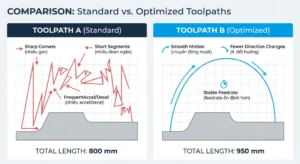
Consider two toolpaths using the same cutting tool, spindle speed, and programmed feedrate.
Toolpath A
- 800 mm total length
- Many short linear segments
- Frequent direction changes
- Several sharp corners
Toolpath B
- 950 mm total length
- Smoother continuous motion
- Fewer abrupt direction changes
- More consistent cutter engagement
Although Toolpath B is 150 mm longer, it may produce a shorter actual cycle time because the machine can maintain a higher percentage of the programmed feedrate.
Modern high-speed machining strategies are specifically designed around this principle. For example, adaptive clearing uses smoother tool motion and avoids abrupt directional changes to maintain more consistent cutting conditions.
2D Adaptive Roughing
In other words, distance matters, but machine behavior matters too.
Rapid Movement Does Not Always Mean Maximum Speed
Rapid movement occurs when the tool is not cutting material. Typical rapid movements include:
- Moving between machining regions
- Retracting the tool
- Approaching the workpiece
- Moving between pockets
- Repositioning for another operation
A machine may have a specified rapid traverse rate such as 30,000 mm/min. But that does not mean every short rapid movement will actually be performed at 30,000 mm/min.
For a short movement, the axis may need to:
- Accelerate from a standstill.
- Reach an intermediate velocity.
- Begin decelerating.
- Stop at the target position.
If the movement is too short, the axis may spend most of its time accelerating and decelerating rather than traveling at maximum rapid speed.
This creates an important CAM optimization principle:
Reducing unnecessary repositioning can be more valuable than simply reducing the distance of each individual movement.
For example, a toolpath with several short retracts and repositioning moves may have a relatively small total rapid distance but still consume considerable time.
CAM programmers therefore need to examine:
- Number of retracts
- Linking moves
- Clearance movements
- Pocket-to-pocket transitions
- Lead-in and lead-out movements
- Stay-down opportunities
Acceleration and Deceleration Can Dominate Actual Cycle Time
A CNC machine cannot instantly change from one movement to another.
Acceleration and deceleration become particularly important when a toolpath contains:
- Sharp corners
- Small-radius arcs
- Short linear segments
- Frequent direction changes
- Dense NC blocks
- High-curvature surfaces
- High-precision finishing movements
Imagine driving a car.
A long, smooth road allows the vehicle to maintain a high speed.
A shorter road filled with sharp corners requires constant braking and acceleration.
CNC machines behave in a similar way.
A toolpath that looks shorter in a CAM simulation may force the machine to continuously change velocity. The result can be a lower actual average feedrate.
This is particularly important for complex 3D machining.
When CAM software approximates complex surfaces using many small line segments, the resulting NC program can contain a very high number of blocks. If the controller cannot process those blocks quickly enough, the machine may not be able to maintain the programmed feedrate.
Therefore, toolpath optimization is not simply about generating more accurate geometry.
It is also about generating machine-executable motion.
Machine Dynamics Directly Affect Cycle Time
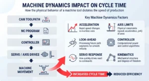
Two CNC machines can execute the same NC program and produce different cycle times.
Why?
Because machine dynamics are different.
Important factors include:
- Axis acceleration limits
- Axis velocity limits
- Machine rigidity
- Controller processing capability
- Look-ahead capability
- Servo response
- Interpolation performance
- Spindle characteristics
- Table and spindle mass
- Workpiece mass
- Fixture rigidity
A CAM simulation may calculate tool motion based primarily on programmed parameters and geometric information. The actual CNC machine, however, must physically execute those commands.
This creates a fundamental distinction:
CAM toolpath time is an estimate of programmed motion. Actual cycle time is the result of programmed motion interacting with a physical machine.
For this reason, an optimized toolpath should be developed with the target machine in mind.
A toolpath that works efficiently on one high-speed machining center may not perform the same way on an older machine with lower acceleration and a slower controller.
The best toolpath is therefore not necessarily the shortest one.
It is the one that is appropriate for the specific machine, controller, tooling, material, and workholding setup.
Programmed Feedrate Is Not the Same as Actual Feedrate
Feedrate in CAM software represents the speed requested by the programmer.
Actual machine feedrate can be lower.
The machine may reduce motion speed because of:
- Axis acceleration limits
- Frequent direction changes
- Small-radius geometry
- Sudden changes in cutter engagement
- Controller limitations
- Machine protection functions
- Surface-quality requirements
This means that a program showing a feedrate of 8,000 mm/min does not necessarily mean the tool spends the entire cutting operation at 8,000 mm/min.
For cycle-time optimization, engineers should consider at least three different parameters:
Programmed Feedrate
The feedrate specified in the CAM program.
Actual Feedrate
The feedrate the machine can physically maintain.
Feedrate Utilization
The percentage of cutting time during which the machine operates close to the programmed target.
This distinction is especially important when comparing two toolpaths.
A shorter path with an average actual feedrate of 4,000 mm/min may be slower than a longer path that maintains 7,000 mm/min for most of its cutting time.
A high feedrate on the screen has limited value if the machine cannot maintain it during actual cutting.
Tool Engagement Is a Major Driver of Machining Performance
Tool engagement describes how much of the cutting tool is engaged with the workpiece.
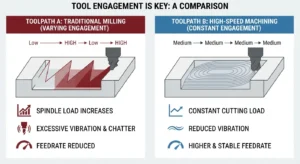
When engagement changes suddenly, cutting forces can change rapidly.
This can occur when the tool:
- Enters a pocket corner
- Cuts into remaining stock
- Moves from a thin region into a thicker region
- Encounters uneven stock
- Transitions between machining strategies
A sudden increase in engagement can result in:
- Higher cutting forces
- Increased spindle load
- Chatter
- Tool deflection
- Increased heat
- Reduced tool life
- Feedrate reduction
This is why modern high-efficiency milling strategies often focus on maintaining a more consistent cutter engagement rather than simply minimizing the cutting distance.
Adaptive clearing is one example. Its toolpath is designed to maintain a controlled engagement level and avoid sudden engagement spikes.
The practical result is important:
A longer toolpath with stable engagement can remove material more efficiently than a shorter toolpath with unstable cutting conditions.
Short Toolpath vs. Optimized Toolpath
| Parameter | Short but Unstable Toolpath | Longer but Optimized Toolpath |
|---|---|---|
| Total path length | Lower | Higher |
| Direction changes | Frequent | Smoother |
| Acceleration/deceleration | Frequent | Reduced |
| Actual feedrate | Often lower | More consistent |
| Tool engagement | Variable | More controlled |
| Cutting load | Unstable | More predictable |
| Vibration risk | Potentially higher | Potentially lower |
| Cycle time | May be longer than expected | May be shorter |
| Tool wear | Potentially higher | Better controlled |
| Production stability | Lower | Higher |
This comparison illustrates why “shorter” and “faster” are not synonymous in CNC programming.
The objective is not to minimize every millimeter of tool movement.
The objective is to maximize productive machine motion.
How Should Engineers Evaluate a CNC Toolpath?
Instead of comparing only total toolpath length, CAM engineers should evaluate the toolpath systematically.
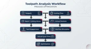
1. Analyze Cutting Time
First, determine how much of the cycle is actually spent removing material.
Separate:
- Cutting time
- Air cutting
- Retracts
- Repositioning
- Tool changes
- Other machine movements
A toolpath can appear efficient while spending a significant amount of time moving through non-cutting regions.
2. Analyze Rapid and Linking Movements
Review:
- Rapid moves between pockets
- Retract distances
- Clearance planes
- Lead-in and lead-out
- Repositioning between operations
- Stay-down opportunities
The goal is not simply to reduce rapid distance, but to reduce unnecessary rapid events.
3. Compare Programmed and Actual Feedrate
Examine how the machine behaves in:
- Tight corners
- Small arcs
- Short line segments
- High-curvature regions
- Areas with changing stock conditions
If the machine repeatedly slows down, increasing the programmed feedrate alone may not solve the problem.
The toolpath itself may need to be redesigned.
4. Evaluate Tool Engagement
Look for sudden changes in cutting load, particularly around:
- Pocket corners
- Entry moves
- Remaining stock
- Deep cavities
- Transitions between machining strategies
Consistent engagement generally provides a more predictable cutting process.
5. Simulate Using the Actual Machine Configuration
For production work, simulation should consider more than the cutting geometry.
Important inputs include:
- Machine kinematics
- Axis limits
- Tool and holder geometry
- Fixture
- Workpiece
- Rotary axes
- Clearance
- Collision conditions
- Post-processor behavior
This becomes especially important for multi-axis machining, where machine configuration and kinematics can significantly affect the final NC program.
6. Validate Against Actual Cycle Time
CAM simulation provides a valuable reference, but the final benchmark should be the actual machine.
After posting the program for the target machine, engineers should compare:
CAM estimated time → NC program → Machine cycle time
This feedback loop can reveal where time is actually being lost.
For production environments, the goal should be continuous improvement rather than optimizing the CAM simulation number alone.
CAM Optimization Is About the Entire Manufacturing System
Toolpath optimization should not be isolated from the broader manufacturing engineering process.
A productive CAM workflow connects:
CAD → CAM → Post-Processing → Machine Simulation → CNC → Inspection
The CAD model defines the geometry.
CAM translates that geometry into machining strategies.
The post-processor converts the toolpath into machine-specific NC code.
Machine simulation verifies whether the program can be executed safely.
The CNC machine performs the actual cutting.
Inspection then provides feedback on dimensional accuracy and manufacturing quality.
This CAD–CAM connection is particularly important for complex components, molds, dies, and automotive parts.
For projects involving reverse engineering, for example, the digital workflow can progress from physical part → 3D scan → CAD reconstruction → validation → CAM → CNC manufacturing.
How TAS US Approaches CAM Programming and Toolpath Optimization
For manufacturers, CAM programming is not simply about generating a toolpath that reaches every surface.
The real objective is to create a machining process that is:
- Efficient
- Stable
- Manufacturable
- Safe
- Appropriate for the target CNC machine
- Consistent with the required quality
At TAS US, our CAM programming services focus on connecting programming decisions with real manufacturing conditions.
Our CAM capabilities can support:
CNC Programming
Development of CNC machining programs for complex components and manufacturing applications.
Toolpath Optimization
Optimization of cutting strategies, linking movements, machining sequences, and tool engagement to improve machining efficiency.
3-Axis and 5-Axis Programming
Development of machining strategies for complex geometries, including multi-axis applications where machine kinematics and collision avoidance become critical.
CAM Simulation and Verification
Verification of tool motion, workpiece interaction, tooling, fixtures, and machine conditions before production.
Mold and Die Machining
CAM programming and machining strategy development for molds, dies, and complex components requiring controlled surface quality and dimensional accuracy.
Manufacturing Process Optimization
Evaluation of machining sequences, tooling strategies, and production conditions to identify opportunities for reducing unnecessary machining time and improving process stability.
Conclusion: The Fastest Toolpath Is Not Always the Shortest One
A shorter CNC toolpath can reduce cutting distance, but toolpath length alone does not determine machining performance.
Actual cycle time is influenced by:
- Toolpath geometry
- Acceleration and deceleration
- Rapid and linking movements
- Machine dynamics
- Controller capability
- Actual feedrate
- Tool engagement
- Cutting conditions
- Machine kinematics
- Tooling and workholding
The most effective toolpath is one that allows the machine to maintain stable, productive motion while controlling cutting forces and maintaining the required part quality.
In some cases, that means accepting a slightly longer toolpath to achieve:
- Smoother machine motion
- More consistent feedrate
- Stable tool engagement
- Fewer unnecessary retracts
- Lower cutting-load variation
- Better tool life
- More predictable cycle time
The goal of CAM optimization is not to make the toolpath as short as possible. It is to make the manufacturing process as efficient as possible.
If your actual CNC cycle time is significantly higher than the time predicted by your CAM software, the problem may not be the total toolpath length.
It may be the way the toolpath interacts with the machine.
TAS US provides CAM programming, CNC toolpath optimization, simulation, and manufacturing engineering support based on the part geometry, tooling, material, machining strategy, and target machine.
Looking to reduce machining time or improve CNC process stability? Contact TAS US to discuss your CAM programming and toolpath optimization requirements.
No responses yet