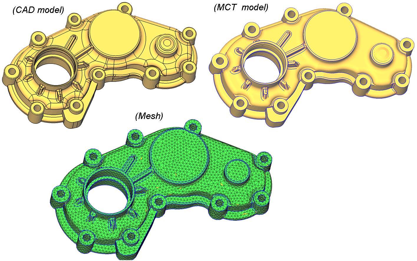
A highly detailed CAD model may be ideal for product design and manufacturing, but that does not automatically make it suitable for engineering simulation. When engineers transfer geometry directly into a CAE workflow, unnecessary features can create poor-quality meshes, increase computational costs, and complicate result interpretation.
The challenge is not simply to preserve every geometric detail. It is to prepare a model that accurately represents the physical behavior being investigated. Understanding the difference between CAD geometry and CAE geometry helps engineering teams improve simulation efficiency without sacrificing the accuracy required for technical decisions.
1. CAD Geometry and CAE Geometry Serve Different Purposes
Computer-Aided Design (CAD) and Computer-Aided Engineering (CAE) are closely connected, but they serve different engineering objectives.
CAD is primarily used to design components, define dimensions, document product specifications, and prepare models for manufacturing and assembly. Detailed features such as fillets, chamfers, threads, mounting holes, and surface details may be essential for these purposes.
CAE uses geometric models to evaluate physical behavior through methods such as Finite Element Analysis (FEA) and Computational Fluid Dynamics (CFD). Engineers use these methods to investigate structural strength, deformation, vibration, heat transfer, and fluid flow.
Because the objectives differ, a geometry that is appropriate for manufacturing may require modification before it can be used effectively in simulation.
| Engineering consideration | CAD geometry | CAE geometry |
|---|---|---|
| Primary objective | Design, documentation, and manufacturing | Physical simulation and engineering evaluation |
| Geometric detail | Preserves product and manufacturing features | Retains features relevant to the physics |
| Model preparation | Focuses on design intent and manufacturability | Focuses on mesh quality and computational efficiency |
| Desired outcome | Production-ready design data | Reliable, interpretable simulation results |
This distinction does not mean CAE models should always be less detailed. Instead, the appropriate level of detail depends on the engineering question, the physical phenomenon, and the required accuracy.
As explained in Ansys’s guide to improving FEA models, model simplification is an important part of building an efficient simulation model. Unnecessary complexity can make analysis more difficult without providing meaningful improvements in results.
2. Why More Geometric Detail Can Produce Worse Simulation Results
A complex CAD model does not automatically produce an inaccurate simulation. However, unnecessary or poorly represented details can introduce avoidable numerical and computational challenges.
2.1. Small features can compromise mesh quality
FEA and CFD require the computational domain to be discretized into elements or cells. The quality and distribution of this mesh influence numerical accuracy, stability, and computational cost.
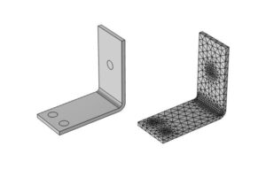
Small fillets, narrow gaps, tiny holes, thin surfaces, and short edges can force the mesher to create very small elements in localized regions. When these features are surrounded by much larger geometry, the resulting mesh may contain poorly shaped elements or abrupt changes in element size.
Such conditions can increase discretization error or make convergence more difficult, depending on the solver, element formulation, and problem being analyzed.
For example, consider a mechanical bracket containing numerous small cosmetic fillets. If the objective is to evaluate overall stiffness under a specified load, many of these fillets may contribute little to the result. Retaining all of them can nevertheless complicate mesh generation.
The solution is not to remove every fillet. Engineers should preserve features that influence the response being measured and simplify those that do not.
2.2. Unnecessary detail increases computational cost
A more complicated model often requires additional preprocessing, mesh elements, memory, and solver time.
This becomes particularly important when engineering teams must evaluate multiple design iterations, loading conditions, or material configurations. If every simulation begins with an unnecessarily detailed model, the accumulated preprocessing and computational effort can slow the entire development process.
For structural analysis, simplifying insignificant components or representing fasteners through appropriate equivalent connections may reduce model complexity. For CFD, removing irrelevant external details and preparing a clean fluid domain can make mesh generation more manageable.
The objective is to allocate computational resources to the regions where the physics requires them, rather than spending them on geometry that does not meaningfully affect the engineering decision.
2.3. Geometric defects can create modeling problems
CAD data transferred between software platforms may contain gaps, overlapping surfaces, duplicate faces, sliver faces, or other geometric inconsistencies.
These issues can interfere with surface stitching, volume extraction, contact definition, and mesh generation. In CFD, an open or incomplete boundary can prevent the creation of a valid fluid volume. In structural analysis, incorrect interfaces between components may affect load transfer or contact behavior.
Geometry cleanup is therefore more than a cosmetic step. It is part of establishing a computational model that represents the intended physical system.
Engineers can refer to Cadence’s technical discussion of geometry challenges in CFD meshing for further information on geometry preparation and mesh generation.
2.4. A detailed model can create false confidence
One of the most important misconceptions in simulation is that visual complexity indicates engineering accuracy.
A model may reproduce every visible component while still producing unreliable results because of incorrect material properties, unrealistic boundary conditions, inappropriate contact definitions, or inaccurate loading assumptions.
For example, a detailed bolted assembly will not necessarily predict joint behavior correctly if bolt preload, friction, contact conditions, or support constraints are incorrectly defined.
Simulation accuracy depends on the quality of the entire modeling process—not simply the number of geometric features or mesh elements.
3. Which CAD Features Can Usually Be Removed?
The decision to simplify geometry should be based on engineering relevance rather than appearance alone.
Depending on the analysis objective, the following features are often candidates for removal or idealization:
- Cosmetic features: Logos, engraved text, decorative grooves, and surface markings that do not influence the physical response.
- Small fillets and rounds: Features outside critical stress regions that have negligible influence on the quantities being evaluated.
- Minor chamfers: Edge treatments that do not significantly affect stiffness, contact, flow, or heat transfer.
- Small holes and threads: Features that do not affect the load path, local stress, leakage, or other relevant physical behavior.
- Noncritical fastener details: Thread geometry, washers, and detailed bolt features that can be represented adequately using simplified connections.
- Insignificant components: Parts that have negligible influence on the analysis and can be omitted or represented through equivalent mass or stiffness where appropriate.
For example, in a global stiffness analysis of a support bracket, removing small cosmetic grooves may reduce geometric complexity without materially changing the result.
However, if a hole defines a critical mounting interface or a fillet lies in a high-stress region, removing that feature could change the predicted response.
The key principle is to simplify deliberately, with a clear understanding of what each feature contributes to the analysis.
4. Which Geometric Features Must Be Preserved?
Some features directly control stress distribution, stiffness, contact behavior, or fluid and thermal performance. Removing them without justification can undermine the validity of a simulation.
Stress concentrations and fatigue-critical regions
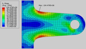
Notches, holes, fillets, and abrupt section changes can produce local stress concentrations. These features may be essential when evaluating fatigue life, crack initiation, local yielding, or component durability.
If the objective is to investigate local stress near a mounting hole, the hole geometry and relevant surrounding details must be represented adequately. Mesh refinement may also be necessary to resolve the local stress field.
Contact interfaces and load paths
Contact surfaces, bolted joints, weld regions, and component interfaces can determine how loads move through an assembly.
Simplified representations are possible, but they must preserve the relevant stiffness, constraints, and load-transfer mechanisms. A simplified bolt connection, for instance, may be suitable for global stiffness evaluation but insufficient for investigating detailed thread stresses.
Thin walls and thickness transitions
Wall thickness affects stiffness, buckling behavior, thermal response, and mass distribution. Thin structures may be represented using shell elements rather than fully solid geometry when the assumptions behind the shell formulation are appropriate.
Abrupt thickness changes and local reinforcements may need to be retained if they significantly influence the response.
Flow passages and thermal interfaces
For CFD and thermal analysis, features such as narrow passages, inlet and outlet geometry, sealing interfaces, cooling channels, and surface details affecting heat transfer may be critical.
A small gap that appears insignificant in a CAD assembly can dominate leakage or flow behavior. Similarly, a geometric detail that influences local turbulence or pressure loss may need to remain in the model.
The correct simplification strategy therefore depends on the physical phenomenon under investigation, not solely on geometric size.
5. A Practical CAD-to-CAE Geometry Preparation Workflow
A reliable workflow begins with the analysis objective and progresses through geometry preparation, meshing, and validation.
Step 1: Define the engineering question
Before modifying geometry, identify what the simulation must determine.
Is the objective to evaluate global stiffness, local stress, fatigue life, crash deformation, natural frequencies, heat transfer, or fluid pressure drop?
Each objective requires a different level of geometric fidelity. A model suitable for a global structural assessment may not be suitable for local fatigue evaluation.
Step 2: Identify critical regions
Locate the areas expected to control the result, such as mounting points, contact interfaces, stress concentrations, thin sections, welds, and flow restrictions.
These regions should guide decisions about which features to retain and where additional mesh resolution may be necessary.
Step 3: Repair and clean the geometry
Inspect the imported model for gaps, overlaps, duplicate surfaces, sliver faces, and invalid bodies.
Repairing these issues before meshing can improve the robustness of the preprocessing workflow and help ensure that the computational domain represents the intended physical geometry.
For CFD, verify that the required fluid volume can be extracted and that the relevant boundaries are properly defined.
Step 4: Simplify and idealize the model
Remove insignificant features and components based on the analysis requirements. Where appropriate, replace detailed geometry with equivalent representations, such as beam elements, shell elements, or simplified fastener connections.
Every simplification should have an engineering rationale. Document assumptions that could affect the interpretation of the results.
Step 5: Generate a mesh appropriate to the physics
Select element types and mesh sizes according to the model geometry, solver requirements, and quantities of interest.
Use local refinement around critical holes, contact regions, sharp gradients, and stress concentrations where necessary. Avoid refining the entire model uniformly when only specific regions require additional resolution.
For CFD, consider boundary-layer resolution, near-wall behavior, and the flow features that must be captured.
Cadence provides an overview of these principles in its technical resource on meshing and mesh generation.
Step 6: Verify and validate the results
Review mesh quality, boundary conditions, material properties, contact definitions, and solver convergence.
Perform a mesh convergence study when appropriate by comparing key outputs across progressively refined meshes. For structural problems, compare relevant quantities such as displacement, reaction forces, and stress away from mathematical singularities. For CFD, examine quantities such as pressure drop, mass flow, and forces on relevant surfaces.
Where possible, compare simulation results with analytical calculations, physical testing, or previously validated models.
A converged solution is not automatically a physically correct solution. Verification and validation must address both numerical behavior and whether the model adequately represents reality.
6. Common CAD-to-CAE Mistakes to Avoid
Even experienced engineering teams can encounter problems when geometry preparation is treated as a routine file-conversion task.
Common mistakes include:
- Importing the original CAD assembly into every simulation without evaluating its purpose.
- Removing all fillets and holes to accelerate meshing, including features that control local stress.
- Modeling every bolt and thread in detail when an equivalent connection would be sufficient.
- Assuming that a higher element count guarantees better accuracy.
- Ignoring contact, material properties, loading assumptions, or boundary conditions while focusing exclusively on geometry.
- Simplifying a model without documenting the assumptions or checking how those changes affect key results.
A more effective approach combines engineering judgment with mesh-quality assessment and sensitivity checks. The goal is not the simplest possible model, but the simplest model that adequately captures the physics relevant to the engineering decision.
7. How TAS US Supports CAD and CAE Engineering Workflows
Preparing CAD geometry for simulation requires an understanding of both product design and numerical analysis. Decisions made during geometry cleanup can influence meshing efficiency, model setup, and the reliability of downstream engineering evaluations.
TAS US supports engineering teams through CAD and CAE-related services, helping manufacturers address design and analysis requirements across product development and manufacturing workflows.
Depending on project scope, engineering support can include:
- CAD modeling and geometry preparation: Organizing and refining engineering geometry for downstream applications.
- CAE model preparation: Reviewing geometry, identifying unnecessary features, and preparing models for appropriate simulation workflows.
- FEA and engineering analysis: Supporting structural evaluations of stress, deformation, stiffness, and other project-specific performance requirements.
- Engineering workflow coordination: Aligning geometry preparation with analysis objectives and manufacturing considerations to reduce avoidable rework.
The appropriate level of support depends on the component, available design data, simulation requirements, and expected deliverables. Engineering assumptions and analysis limitations should be defined clearly for each project.
Learn more about TAS US and its engineering outsourcing approach, or explore its CAM programming services for related manufacturing engineering support.
Conclusion: Build the Right Model, Not Just a Detailed One
CAD and CAE serve different purposes, and effective simulation requires geometry prepared for the physical problem being solved.
Unnecessary details can increase preprocessing time, complicate mesh generation, and consume computational resources without improving the results that matter. At the same time, removing critical features can distort stress distribution, contact behavior, thermal performance, or fluid flow.
The most reliable approach is to define the engineering objective first, preserve the geometry that controls the relevant physics, simplify what does not, and verify the resulting model through appropriate mesh and solution checks.
CAE does not need a CAD model that reproduces every product detail. It needs a model that represents the physics accurately enough to support sound engineering decisions.
Need support preparing CAD geometry for FEA or CFD? Contact TAS US to discuss your engineering requirements and identify an appropriate geometry-preparation and simulation workflow.
No responses yet