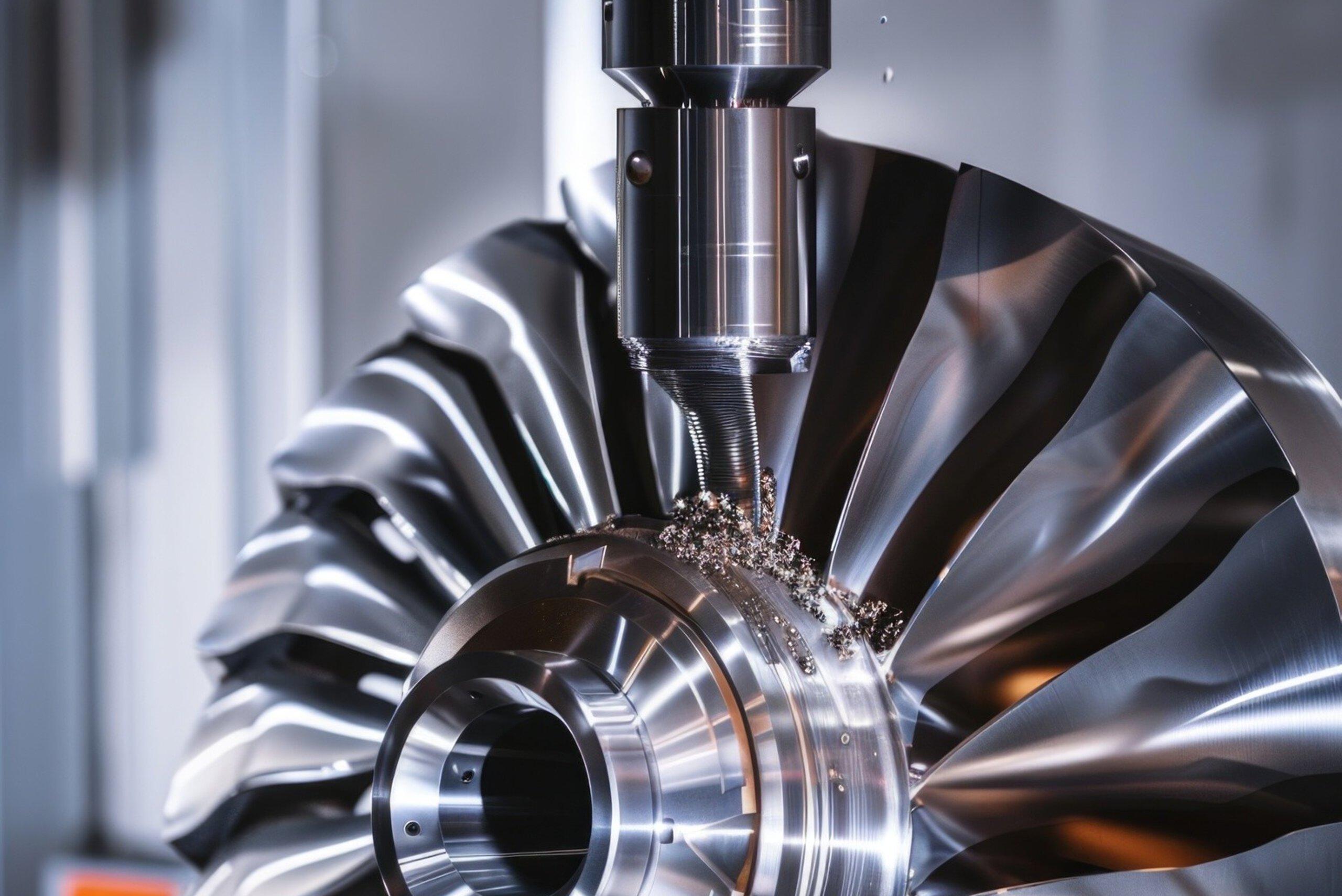
Choosing between 3-axis, 3+2, and 5-axis CNC machining is not simply a question of machine capability. The same component may be manufactured using all three approaches, yet the results can differ significantly in cycle time, tooling requirements, setup count, collision risk, surface finish, and dimensional accuracy.
A complex component with angled holes, deep pockets, or sculptured surfaces may benefit from multi-axis machining. However, using a 5-axis machine does not automatically make a process faster, cheaper, or more accurate. For parts with straightforward geometry, a well-planned 3-axis process may remain the most productive option.
The real engineering challenge is selecting the right degree of motion freedom for the part’s geometry, tolerance requirements, and manufacturing constraints.
For CNC programmers and manufacturing engineers, this decision requires more than comparing machine specifications. It involves evaluating tool accessibility, tool orientation, fixture rigidity, machine kinematics, and the reliability of the entire CAM workflow.
This article explains what changes when moving from 3-axis to 3+2 and simultaneous 5-axis machining—and how to select the appropriate strategy for a real manufacturing application.
1. Understanding 3-Axis, 3+2, and Simultaneous 5-Axis Machining
Although these methods use different motion strategies, their primary purpose is the same: to remove material efficiently while meeting the component’s geometric and dimensional requirements.
| Machining method | Motion during cutting | Typical applications |
|---|---|---|
| 3-Axis | Linear X, Y, and Z motion | Prismatic parts, flat surfaces, pockets, and accessible holes |
| 3+2 / Indexed 5-Axis | Rotary axes position the tool or workpiece, then remain fixed during cutting | Angled holes, multi-face components, and inclined pockets |
| Simultaneous 5-Axis | Three linear and two rotary axes coordinate continuously during cutting | Impellers, turbine blades, complex molds, and sculptured surfaces |
The distinction between indexed and simultaneous machining is fundamental. In 3+2 machining, the rotary axes establish a fixed cutting orientation before a machining operation begins. The cutting tool then follows a conventional three-axis toolpath.
In simultaneous 5-axis machining, the rotary and linear axes can move together throughout the cutting operation, allowing the tool orientation to change continuously as it follows the part geometry.
Autodesk provides further explanations of these approaches in its 5-axis machining guide.
2. Degrees of Freedom: What Actually Changes?
The main difference between these strategies is not simply the number of available axes. It is how those axes are used to control the cutting tool relative to the workpiece.
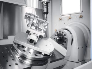
3-axis machining: Fixed tool orientation
A conventional three-axis milling machine uses linear X, Y, and Z motion. The tool axis typically remains aligned with the Z-axis of the active work coordinate system.
This approach works well when the required surfaces and features are accessible from a suitable direction. It also supports relatively straightforward programming, setup planning, and machine operation.
However, when a part contains features on multiple faces, the workpiece may need to be repositioned or transferred to another setup.
3+2 machining: Position first, then cut
In 3+2 machining, two rotary axes position the tool or workpiece at a selected angle. Once the orientation is established, the rotary axes remain fixed while the three linear axes perform the cutting movements.
This method is particularly useful for machining inclined surfaces, angled holes, and features distributed across multiple faces.
Importantly, 3+2 is an indexed machining strategy, not simply a less sophisticated version of simultaneous 5-axis machining. It offers a different balance between accessibility, rigidity, and programming complexity.
Simultaneous 5-axis machining: Continuous tool orientation
Simultaneous 5-axis machining coordinates three linear axes with two rotary axes. The cutting tool can change its orientation while following complex surfaces or navigating restricted areas.
This flexibility is valuable when a fixed tool orientation cannot maintain the required contact conditions or provide sufficient clearance throughout the cutting path.
However, greater motion freedom also introduces additional programming and verification requirements, particularly when machine kinematics and rotary-axis limits affect the resulting toolpath.
3. Setup Reduction and Fixturing: Where Manufacturing Costs Accumulate
One of the most important benefits of multi-axis machining is the potential to reduce the number of setups.
On a 3-axis machine, a component with features on several sides may require repeated unclamping, repositioning, and datum alignment. Each additional setup introduces handling time and another opportunity for alignment errors.
These activities also create practical production challenges:
- Additional fixture design and workholding requirements.
- More operator intervention and setup documentation.
- Potential datum transfer errors and tolerance stack-up.
- Increased inspection requirements after repositioning.
- Longer elapsed production time between machining operations.
With 3+2 machining, rotary positioning can provide access to multiple faces without manually reclamping the workpiece for every orientation.
Simultaneous 5-axis machining can offer similar advantages when complex geometry requires continuous changes in tool orientation. Depending on the component and machine configuration, several operations may be completed within one setup.
Reducing setups does not automatically guarantee lower production costs. Programming time, fixture complexity, machine availability, and cycle time must also be considered.
Nevertheless, when multiple setups are the main source of manufacturing inefficiency, a multi-axis strategy can improve process repeatability and reduce non-cutting time.
4. Tool Accessibility and Orientation: The Core CAM Challenge
Tool accessibility is often the deciding factor when selecting between 3-axis, 3+2, and simultaneous 5-axis machining.
The question is not only whether the cutting edge can reach the target surface. The complete tool assembly—including the cutting tool, shank, holder, and spindle—must reach the required position without interfering with the workpiece or fixture.
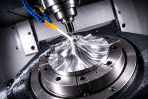
Limitations of 3-axis machining
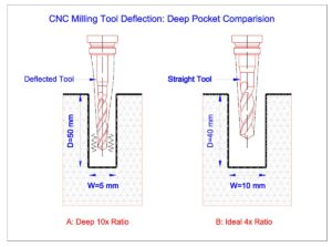
Consider a deep pocket with steep walls. A three-axis approach may require a long-reach end mill to reach the bottom while clearing the surrounding geometry.
A longer tool increases the effective overhang and can make the cutting system more susceptible to deflection and vibration. Depending on the material, cutting parameters, and tool geometry, this can affect dimensional consistency and surface finish.
Some undercuts and angled features may also be inaccessible from the available tool direction.
Advantages of 3+2 machining
Tilting the workpiece or tool can improve access to inclined faces, cross-holes, and pockets that are difficult to machine from the primary orientation.
The fixed orientation can also support a more rigid cutting arrangement than a simultaneous strategy in applications where the tool can be kept short and the rotary axes remain securely positioned.
For many multi-face components, 3+2 provides a practical compromise: fewer setups and improved accessibility without requiring continuous five-axis movement during every cut.
When simultaneous 5-axis becomes valuable
Consider an impeller with curved blades and narrow passages between adjacent surfaces.
A fixed tool orientation may require several operations to reach different regions. The programmer must manage transitions between orientations while maintaining suitable clearance and avoiding gouging.
With simultaneous 5-axis machining, the tool orientation can change continuously along the surface. A suitable CAM strategy can help maintain a more appropriate contact condition and avoid unnecessary tool extension.
The benefit depends on the cutter geometry, toolpath strategy, machine configuration, and cutting conditions. Five-axis motion does not eliminate the need to evaluate tool engagement or cutting forces.
For additional technical context, Autodesk’s tool orientation documentation explains how tool orientation controls the cutting plane and supports multi-axis machining.
5. Collision Risk and Tool Length: More Motion Requires More Control
Collision avoidance is a central consideration in multi-axis CAM programming.
Potential interference can involve the cutting edge, tool shank, holder, spindle head, fixture, or other machine components. A toolpath that appears valid when viewed against the part model may still be unsafe when the complete machine assembly is considered.
In 3-axis machining, common challenges include holder clearance in deep pockets and interference near tall fixtures or steep walls.
In 3+2 machining, indexing the workpiece can improve access, but an unsuitable rotary angle may bring the holder or spindle head into contact with the part or fixture.
Simultaneous 5-axis machining provides more options for changing tool orientation and navigating restricted geometry. However, it also introduces more complex rotary movements and potential interference scenarios.
Five-axis capability does not eliminate collision risk. It expands the available machining options—and increases the importance of verification.
A robust CAM workflow should include:
- Accurate tool, holder, fixture, stock, and machine models.
- Toolpath verification against the intended machining geometry.
- Collision and clearance checks for relevant machine components.
- Machine-aware simulation of rotary-axis movements and limits.
- Post-processor validation and appropriate prove-out before production.
Machine simulation and collision detection help identify risks before NC programs reach the shop floor. Their effectiveness depends on model accuracy, machine configuration, and the capabilities of the simulation environment.
6. Does 5-Axis Machining Deliver Better Accuracy?
Not necessarily. Accuracy depends on the complete manufacturing process, not the number of machine axes.
Multi-axis machining can improve dimensional consistency when it reduces setup changes or enables a more stable cutting arrangement. However, the final result still depends on several interacting factors.
Datum strategy and fixturing: Fewer setups can reduce errors associated with repeated repositioning. The initial datum definition and workholding arrangement must still be reliable.
Tool rigidity and runout: Shorter tool overhangs can reduce deflection and vibration. Tool selection, spindle condition, and runout remain important.
Machine kinematics: Rotary-axis calibration, positioning performance, geometric errors, and thermal effects can influence the resulting part geometry.
Cutting conditions: Feed rate, spindle speed, tool engagement, material properties, and tool wear all affect dimensional results and surface quality.
CAM strategy: Toolpath orientation, stepover, lead and lean angles, linking movements, and gouge avoidance influence the final surface.
For relatively simple prismatic parts, a properly configured three-axis or indexed 3+2 process may achieve the required tolerances without the additional complexity of simultaneous five-axis machining.
For complex freeform surfaces, continuous five-axis motion can offer better control over tool orientation and surface finishing when programmed and validated appropriately.
The engineering principle is straightforward: accuracy comes from controlling the entire process—from datum selection and fixturing to cutting conditions, machine behavior, and CAM verification.
7. CAM Programming Complexity and Workflow Requirements
As machining strategies become more sophisticated, the CAM programmer must account for additional variables.
| CAM consideration | 3-Axis | 3+2 | Simultaneous 5-Axis |
|---|---|---|---|
| Programming complexity | Low to moderate | Moderate | High |
| Tool orientation | Usually fixed | Indexed and fixed during cutting | Continuously coordinated |
| Work coordinate management | Relatively simple | Multiple orientations may be required | Requires careful orientation and kinematic planning |
| Collision verification | Important | Critical for indexed positions and transitions | Critical throughout tool motion |
| Machine simulation | Depends on risk and complexity | Strongly recommended | Essential for a robust workflow |
| Post-processor requirements | Generally simpler | Must support the machine’s rotary configuration | Must correctly handle machine kinematics and simultaneous motion |
For simultaneous five-axis work, generating a geometrically correct toolpath is only part of the task. The CAM programmer must also consider rotary-axis limits, singularities, machine configuration, safe linking moves, and post-processor behavior.
The resulting NC code must be appropriate for the actual machine and controller. A valid CAM toolpath should never be assumed to be production-ready without the necessary verification and machine-specific checks.
8. How to Choose the Right Machining Strategy
The most effective approach begins with the component’s geometry and manufacturing requirements rather than the machine’s maximum capabilities.
Choose 3-axis machining when:
- Most features are accessible from a primary direction.
- The component consists mainly of flat faces, pockets, and conventional holes.
- Multiple setups are not a major source of cost or alignment risk.
- A straightforward programming workflow meets the required tolerances.
Choose 3+2 machining when:
- Features are distributed across multiple faces.
- Angled holes and inclined pockets can be machined at fixed orientations.
- Reducing manual repositioning is a priority.
- A fixed tool orientation provides sufficient access and clearance.
Choose simultaneous 5-axis machining when:
- The component contains complex freeform surfaces, such as turbine blades or impellers.
- Undercuts or restricted access require continuously changing tool orientation.
- A shorter, more rigid tool arrangement can improve machining stability.
- Surface geometry requires continuous tool-axis control.
- The cost or alignment risk associated with multiple setups is significant.
Before making a final decision, evaluate the complete process: machining time, tool and fixture costs, programming effort, machine availability, inspection requirements, and expected production volume.
In some cases, a hybrid strategy is the most effective solution. Roughing and accessible features may be completed using three-axis or indexed operations, while simultaneous five-axis machining is reserved for surfaces that genuinely require it.
9. A Practical Decision Framework for Manufacturing Engineers
Use the following questions during CAM process planning:
| Engineering question | Initial strategy to evaluate |
|---|---|
| Are most features accessible from one direction? | 3-axis |
| Are multiple faces or angled features accessible at fixed orientations? | 3+2 |
| Does the tool need to change orientation continuously along a surface? | Simultaneous 5-axis |
| Are repeated setups creating datum or alignment risks? | 3+2 or 5-axis |
| Does a deep cavity require excessive tool overhang? | Evaluate 3+2 and simultaneous 5-axis |
| Are holder clearance and machine interference major constraints? | Evaluate multi-axis access and validate the complete machine model |
These questions are starting points, not universal rules. The final selection must account for the actual geometry, machine kinematics, tool assembly, workholding, tolerance requirements, and production objectives.
10. Optimize Your CNC Process with TAS US CAM Programming Support
Selecting between 3-axis, 3+2, and simultaneous 5-axis machining requires an integrated understanding of part geometry, cutting tools, fixturing, machine kinematics, and CAM programming.
TAS US supports manufacturers seeking to improve CNC machining workflows through engineering-focused CAM programming and toolpath planning. The appropriate approach depends on the component, available machine capabilities, production requirements, and the level of verification needed.
Our CAM programming services can support activities such as:
- CNC toolpath planning based on part geometry and machining requirements.
- Selection of suitable machining strategies and tool orientations.
- Multi-face machining and setup optimization.
- Toolpath simulation and collision-risk assessment.
- NC program preparation aligned with the specified machine and post-processor requirements.
Rather than defaulting to the machine with the most axes, the goal is to develop a process that balances accessibility, rigidity, accuracy, programming effort, and production efficiency.
Explore our CAM Programming Services to learn more about our engineering support.
Considering a move from 3-axis to 3+2 or simultaneous 5-axis machining? Contact TAS US to discuss your part geometry, machining constraints, and CAM programming requirements.
The right strategy is not necessarily the one with the most axes. It is the one that gives your manufacturing team the necessary tool access, process stability, and repeatable results with the least unnecessary complexity.
No responses yet