In manufacturing quality control, one question comes up repeatedly: Should you use a Coordinate Measuring Machine (CMM) or a 3D scanner for dimensional inspection?
The answer depends on more than measurement accuracy. Engineers must consider part geometry, required tolerances, inspection coverage, production volume, and the purpose of the measurement. Are you verifying critical dimensions for part acceptance, investigating a manufacturing defect, comparing a physical component against CAD, or reconstructing geometry for which no original CAD model exists?
CMMs excel at measuring critical geometric features and verifying tight tolerances, while 3D scanners excel at capturing dense surface data and evaluating overall part geometry.
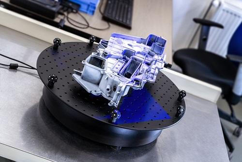
A CMM typically uses a probe to measure selected points or features. An optical 3D scanner captures thousands or millions of surface points, creating a point cloud that can be processed into a mesh for dimensional analysis.
Neither technology is universally superior. The right choice is the one that provides reliable measurement evidence for the engineering decision you need to make.
1. What Is a Coordinate Measuring Machine (CMM)?
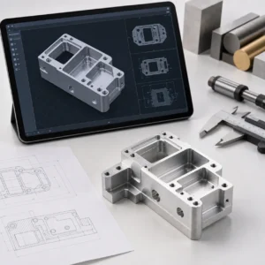
A Coordinate Measuring Machine (CMM) is a metrology system that determines the three-dimensional coordinates of points on a physical part. A conventional tactile CMM uses a contact probe to collect measurements according to a programmed inspection routine.
Measurement software uses these coordinates to establish geometric features and evaluate dimensions against engineering drawings, CAD models, and applicable geometric dimensioning and tolerancing (GD&T) requirements.
CMM inspection is particularly useful for critical features such as:
- Hole diameters, center distances, and positional tolerances.
- Shaft diameters, cylindrical features, and mating surfaces.
- Datum references and geometric relationships.
- Flatness, perpendicularity, parallelism, and other GD&T characteristics.
- Precision-machined components with tightly controlled dimensional requirements.
Key advantages of CMM inspection
1. High accuracy for critical dimensions
A properly selected and calibrated CMM can deliver excellent measurement performance for precision features. Its suitability depends on the machine’s measurement capability, probe configuration, part geometry, environmental conditions, and required uncertainty.
2. Repeatable inspection procedures
Once a measurement routine and fixture setup have been established, a CMM can repeatedly inspect defined features. This makes it valuable for production quality control, incoming inspection, and documented dimensional verification.
3. Strong support for GD&T
CMM software can evaluate geometric features and relationships against specified datums. This is essential when part functionality depends on the position, orientation, or form of a feature rather than its size alone.
4. Established metrology workflows
CMMs are widely used in precision manufacturing environments where inspection procedures, calibration, traceability, and documented acceptance criteria are essential.
For further reference, the International Organization for Standardization provides information on CMM performance verification in ISO 10360-5, which addresses coordinate measuring machines using contact probing systems.
Limitations of CMM inspection
A conventional tactile CMM measures the features included in its inspection routine rather than automatically capturing the entire surface.
Complex parts may require multiple probe orientations, careful fixture design, and additional programming. Deep recesses, narrow gaps, thin walls, and intricate freeform surfaces can also be difficult to access.
Consequently, CMM inspection may become time-consuming when engineers need to evaluate extensive surface deviations or investigate defects whose locations are not known in advance.
2. What Is 3D Scanning for Dimensional Inspection?
Industrial 3D scanning uses optical technologies, such as laser triangulation or structured light, to capture the geometry of a physical object without conventional contact probing.
The scanner records surface data as a point cloud. Depending on the system and workflow, this data can then be processed into a polygonal mesh for alignment, measurement, visualization, and comparison with a reference CAD model.
One of the most valuable applications is CAD-to-part deviation analysis.
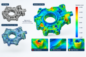
Engineers align the scanned geometry with the nominal CAD model using an appropriate alignment strategy. Inspection software then calculates deviations between the measured surface and the reference geometry, often displaying the results as a color deviation map.
This makes it possible to visualize where a component is oversized, undersized, warped, or otherwise different from its intended geometry.
Key advantages of 3D scanning
1. High surface coverage
Instead of collecting only selected points, a 3D scanner captures a dense representation of accessible surfaces. This is particularly useful for complex plastic housings, castings, stamped panels, molded components, and freeform geometries.
2. Faster data acquisition for complex parts
A scan can capture extensive surface information in a short period, depending on the part size, surface characteristics, scanner, and required coverage. However, scanning time is only one part of the workflow; data processing, alignment, inspection, and reporting must also be considered.
3. Visual identification of manufacturing deviations
Color maps help engineers identify patterns that may be difficult to recognize through isolated dimensional measurements. These patterns can indicate local deformation, warpage, inconsistent machining, or deviations introduced during molding and forming.
4. Support for First Article Inspection (FAI)
When appropriate equipment, software, and inspection procedures are used, 3D scanning can support first-article evaluation by comparing a newly manufactured component with its nominal CAD geometry.
It is especially useful when the inspection objective includes broad surface coverage rather than a limited list of dimensions.
5. Reverse engineering
When the original CAD model is missing, outdated, or incomplete, scan data can provide a geometric reference for reconstructing an editable CAD model. This can support replacement-part development, design recovery, and subsequent manufacturing activities.
For a deeper technical overview, see KEYENCE’s guide to 3D scanning in industrial metrology.
Limitations of 3D scanning
A dense point cloud does not automatically guarantee accurate measurements. Scanner performance varies by equipment, measurement volume, calibration, surface reflectivity, geometry, scanning strategy, and environmental conditions.
Highly reflective, transparent, dark, or difficult-to-access surfaces may require special preparation or alternative measurement strategies.
Data processing also matters. Engineers must select an appropriate alignment method, handle incomplete or noisy data, and define how deviations will be calculated.
Most importantly, a full-surface color map does not automatically establish compliance with every drawing requirement. Critical GD&T characteristics, datum schemes, and acceptance criteria must be evaluated using suitable measurement and analysis methods.
3. CMM vs. 3D Scanning: Key Differences
The following comparison summarizes how each technology fits common manufacturing inspection requirements.
| Evaluation criterion | CMM inspection | 3D scanning |
|---|---|---|
| Measurement method | Contact probing or supported scanning probes | Optical or laser-based surface acquisition |
| Data captured | Selected points and defined geometric features | Dense point cloud and, typically, a processed mesh |
| Accuracy | Often preferred for demanding critical-feature tolerances | Depends on scanner capability, setup, and measurement conditions |
| Surface coverage | Focused on programmed measurement locations | Broad coverage of accessible surfaces |
| GD&T | Well established for defined geometric requirements | Possible with suitable metrology software and validated workflows |
| Complex freeform geometry | Can require extensive programming and probe access | Particularly useful for capturing complex surface geometry |
| Deviation visualization | Feature-based results and supported CAD comparisons | Full-surface color deviation maps |
| Typical applications | Precision dimensions, datums, critical fits, geometric tolerances | Surface inspection, deformation analysis, CAD comparison, reverse engineering |
| Workflow considerations | Programming, probing strategy, fixturing | Scanning, data processing, alignment, analysis |
| Best selection criterion | Critical dimensional verification | Comprehensive surface evaluation |
Important: There is no universal accuracy value that applies to every CMM or 3D scanner. A technology should be selected using the actual measurement requirements and the documented performance of the proposed system.
4. When Should You Choose CMM Inspection?
CMM inspection is generally the stronger choice when acceptance depends on specific dimensions or geometric tolerances that require high-confidence measurement.
Consider a precision-machined aluminum housing with several mounting holes and a tightly controlled shaft bore. The engineer may need to verify bore diameter, hole position relative to a datum reference frame, perpendicularity, and the relationship between mating features.
In this case, a tactile CMM can measure the relevant features directly and evaluate them against the drawing requirements.
Choose CMM when:
- Critical dimensions have very tight tolerances.
- Datum-based GD&T verification is central to acceptance.
- Hole locations, shaft diameters, or mating features determine functionality.
- A customer or quality procedure specifies a particular measurement method.
- Repeatable inspection of defined features is required across production batches.
The key is to verify that the complete measurement process—not just the machine’s advertised specification—is capable of assessing the required tolerances.
5. When Should You Choose 3D Scanning?
3D scanning becomes especially valuable when engineers need to understand the condition of an entire component rather than verify only a small number of predefined dimensions.
Consider an injection-molded plastic housing that does not fit correctly during assembly. The problem could involve local warpage, deformation around mounting bosses, uneven wall geometry, or dimensional changes distributed across the part.
Measuring a few selected points may confirm that some dimensions are out of tolerance, but it may not reveal the overall pattern of deformation.
A 3D scan can capture the accessible surface geometry and compare it with the nominal CAD model. The resulting deviation map helps engineers identify where discrepancies occur and determine which regions require further investigation.
Choose 3D scanning when:
- The part has complex curves, freeform surfaces, or intricate geometry.
- You need broad surface coverage rather than isolated measurements.
- The location or pattern of a dimensional defect is initially unknown.
- You need to compare manufactured parts against nominal CAD geometry.
- First-article evaluation requires detailed surface comparison.
- The original CAD model is unavailable and reverse engineering is required.
For more information on dimensional metrology and measurement uncertainty, consult the National Institute of Standards and Technology (NIST).
6. A Practical Decision Guide for Quality Engineers
When choosing between CMM and 3D scanning, start with the engineering question rather than the equipment.
Scenario A: A few dimensions have very tight tolerances.
Recommended approach: CMM inspection, provided the system and measurement procedure are capable of verifying the specified requirements.
Scenario B: You need to understand how an entire surface deviates from CAD.
Recommended approach: 3D scanning with a defined alignment strategy and CAD deviation analysis.
Scenario C: A complex molded component shows warpage after production.
Recommended approach: 3D scanning to visualize surface deviations, followed by targeted measurements or additional analysis where necessary.
Scenario D: A customer requires documented verification of critical GD&T features.
Recommended approach: Use the measurement method specified by the applicable drawing, customer requirements, and quality procedure. A CMM may be appropriate, but the decision should be requirement-driven.
Scenario E: The part must be inspected and reconstructed into editable CAD.
Recommended approach: 3D scanning combined with reverse engineering. The scan provides the geometric reference, while engineering reconstruction converts that reference into a usable CAD model.
Why a combined approach can be more effective
CMM and 3D scanning are not mutually exclusive technologies.
A combined workflow can use scanning to identify overall deformation and CMM inspection to verify selected critical dimensions. This approach can provide broader diagnostic information without relying on surface data alone for every acceptance decision.
The exact workflow should reflect the drawing, tolerance requirements, production process, inspection budget, and consequences of a measurement error.
7. How TAS US Can Support Your Inspection and Engineering Workflow
Selecting a measurement technology is only the first step. The results must be translated into information that quality, design, and manufacturing teams can use.
TAS US focuses on engineering outsourcing solutions across CAD, CAE, CAM, automation, BIM, and related engineering workflows. For projects involving 3D scanning and reverse engineering, the broader engineering process can connect physical-part data with CAD reconstruction and downstream manufacturing requirements.
Depending on project scope, a typical workflow may include:
- Part assessment: Review the component geometry, available drawings, CAD references, and inspection objectives.
- 3D data acquisition: Capture the physical geometry using an appropriate scanning method.
- Data processing: Prepare the point cloud or mesh for analysis.
- CAD alignment and deviation analysis: Compare the measured geometry with the nominal reference where available.
- Engineering reconstruction: Rebuild an editable CAD model when reverse engineering is required.
- Technical deliverables: Prepare agreed CAD files, dimensional analysis outputs, or engineering documentation.
The deliverables and measurement method should be agreed upon before work begins. Where formal inspection acceptance is required, the project should also define the applicable tolerances, measurement uncertainty expectations, and reporting criteria.
Explore the TAS US website for more information about the company’s engineering capabilities.
Conclusion: Choose the Measurement Method That Fits the Requirement
CMM is not obsolete, and 3D scanning is not a universal replacement for contact measurement.
CMM inspection remains highly valuable for critical dimensions, datum relationships, and demanding GD&T requirements. 3D scanning offers a different advantage: dense surface data that helps engineers evaluate complex geometry, visualize deviations, investigate manufacturing issues, and support reverse engineering.
For many manufacturers, the most effective strategy is to use each technology where it provides the strongest measurement evidence.
Need help deciding between 3D scanning and CMM inspection?
Share your part drawing, specified tolerances, and photos or CAD files with TAS US. Our engineering team can help assess the appropriate inspection or reverse engineering workflow for your component and project requirements.
No responses yet