Reverse Engineering Injection Molds: How to Accurately Compensate for Wear and Restore Original Performance

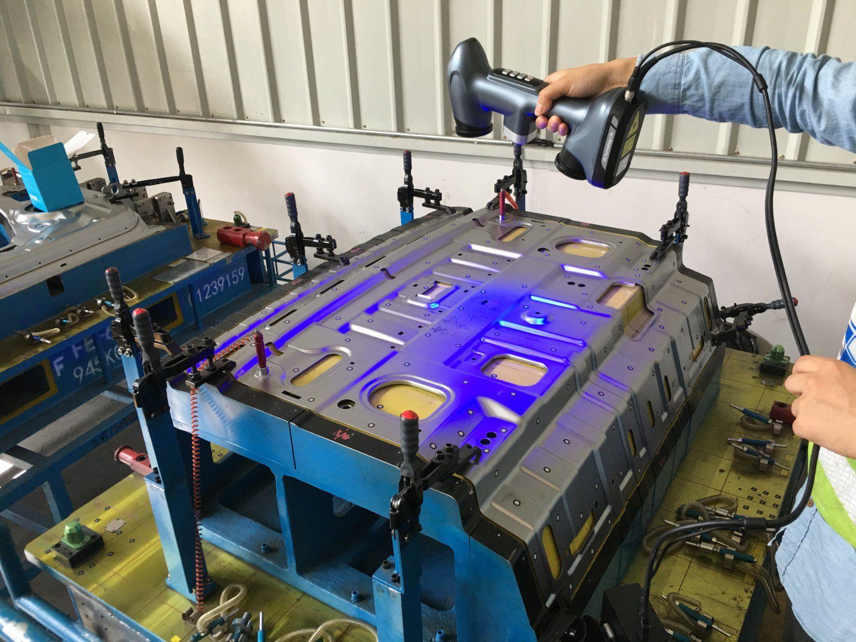
3D scanning and reverse engineering workflow for injection mold restoration and wear analysis

Injection molds are among the most valuable assets in any plastics manufacturing operation. A well-designed mold can run hundreds of thousands—or even millions—of production cycles while maintaining consistent part quality.

However, no mold lasts forever.

Over time, critical mold surfaces begin to wear. Cavity edges become rounded, shut-off surfaces lose precision, venting features degrade, and parting lines gradually change. Even minor geometric deviations can lead to dimensional inconsistencies, flash, short shots, warpage, and increased scrap rates.

The challenge becomes even greater when original CAD files are missing, outdated, or no longer reflect years of modifications made during production.

In these situations, many manufacturers attempt to repair molds based on experience, manual measurements, or visual inspection. Unfortunately, this often introduces additional errors and can move the mold even further away from its intended geometry.

A more reliable approach is to combine 3D scanning, deviation analysis, and reverse engineering to accurately identify wear patterns and restore the mold to a functional, production-ready condition.

At TAS US, we help manufacturers recover accurate digital models from existing molds, analyze wear with precision, and generate CAD data that supports mold repair, refurbishment, and long-term maintenance planning.

What Is Reverse Engineering for Injection Molds?

Reverse engineering is the process of capturing the physical geometry of an existing mold and converting it into a usable digital CAD model.

Unlike simple duplication, reverse engineering aims to understand the actual condition of the mold and reconstruct the geometry required for future manufacturing or restoration.

The process typically involves:

  • Capturing the mold using high-resolution 3D scanning
  • Creating a digital representation of the mold geometry
  • Comparing scan data with available CAD models or drawings
  • Identifying worn regions and geometric deviations
  • Reconstructing surfaces and critical features
  • Generating updated CAD models for repair or remanufacturing

This workflow enables manufacturers to move from assumptions and manual measurements to data-driven decision-making.

Learn more about TAS US’s 3D scanning capabilities through our 3D Scanning Services page and how scan data is transformed into engineering-ready CAD through our Reverse Engineering Services page.

How Mold Wear Impacts Product Quality

Many mold issues develop gradually, making them difficult to detect until production quality begins to suffer.

Common wear-related problems include:

Dimensional Drift

Repeated production cycles can slowly alter cavity dimensions. Even a few thousandths of an inch of wear may push molded parts outside specification.

Flash Formation

Worn shut-off surfaces and parting lines can allow molten plastic to escape, creating flash and increasing finishing requirements.

Incomplete Filling

Degraded venting features can trap air during injection, resulting in short shots and inconsistent filling.

Surface Defects

Wear on textured or polished surfaces can negatively affect cosmetic appearance and product consistency.

Assembly Problems

When critical features no longer match their intended geometry, downstream assembly operations may experience fitment issues and increased rejection rates.

According to guidance from the National Institute of Standards and Technology (NIST), dimensional accuracy and process control are fundamental components of manufacturing quality and repeatability.

The longer mold wear goes unaddressed, the more expensive the resulting production issues become.

Why Traditional Repair Methods Often Fail

When original design data is unavailable, many repair teams rely on manual measurements or historical experience.

While these methods can sometimes address obvious damage, they frequently introduce new inaccuracies.

Common mistakes include:

Measuring Only Selected Points

Traditional inspection tools capture individual dimensions but often miss complex surface deviations across the entire cavity.

Assuming Uniform Wear

Mold wear rarely occurs evenly. High-pressure regions, gate areas, shut-offs, and moving components typically wear at different rates.

Rebuilding Based on Estimates

Without accurate deviation analysis, technicians may add too much or too little material during repair.

Skipping Verification

Many repairs are completed without validating the final geometry against a digital reference model.

As a result, manufacturers often enter a cycle of repeated repairs that increase downtime and maintenance costs.

The Role of 3D Scanning in Mold Wear Compensation
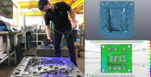
Engineer performing 3D scanning on an injection mold for reverse engineering and inspection

Modern 3D scanning technology provides a comprehensive picture of the mold’s current condition.

Instead of measuring dozens of points, manufacturers can capture millions of data points across the entire mold surface.
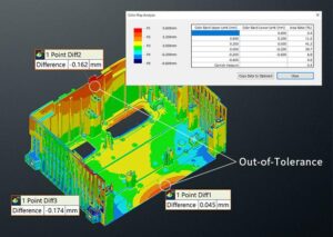
The resulting scan data creates a highly detailed digital representation that can be analyzed with engineering software to identify:

  • Wear locations
  • Surface degradation
  • Geometric distortion
  • Missing material
  • Dimensional deviations
  • Previous undocumented modifications

This information forms the foundation for accurate reverse engineering and restoration.

Step-by-Step Process for Accurate Mold Wear Compensation

1. Mold Preparation

The mold is first cleaned to remove oil, debris, oxidation, and production residue.

Proper preparation ensures the scan accurately captures the actual geometry rather than surface contamination.

2. High-Resolution 3D Scanning

Using advanced optical scanning systems, engineers capture the complete mold geometry.

This process records millions of measurement points and creates a dense point cloud or mesh representation of the mold.

The resulting dataset provides a level of detail that is difficult to achieve with traditional measurement techniques.

3. CAD Comparison and Deviation Analysis

If original CAD data exists, scan data can be directly compared against the design model.

Color deviation map highlighting wear areas on an injection mold compared with CAD data

Engineers generate color-mapped deviation reports that visually highlight:

  • Material loss
  • Excess material
  • Surface deformation
  • Critical dimensional changes

When original CAD files are unavailable, reverse engineering techniques are used to reconstruct the intended geometry.

4. Identification of Wear Zones

Not all deviations require correction.

Engineering analysis focuses on functional areas such as:

  • Cavity surfaces
  • Core features
  • Shut-offs
  • Parting lines
  • Vent locations
  • Alignment features

This allows repairs to target actual performance issues rather than making unnecessary modifications.

5. CAD Reconstruction and Compensation

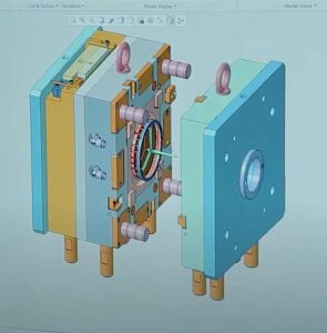
Reverse engineered CAD model reconstructed from 3D scan data of an injection mold

Once wear patterns are identified, engineers rebuild affected surfaces within CAD software.

Instead of simply copying the worn geometry, the model is adjusted to compensate for material loss and restore intended functionality.

This is the critical difference between duplication and engineering-driven restoration.

The goal is not merely to recreate what currently exists but to recover the geometry required for proper molding performance.

6. Validation and Quality Verification

Before repair work begins, the reconstructed model can be validated through additional inspection and engineering review.

This verification process reduces risk and improves confidence that repairs will deliver the desired production results.

When Original Drawings No Longer Exist

Many manufacturers face a common challenge:

The mold still exists, but the original engineering data does not.

This may happen because:

  • The mold was built decades ago
  • Suppliers are no longer available
  • CAD files were lost during ownership changes
  • Multiple undocumented repairs have occurred over time

In these cases, 3D scanning and reverse engineering become essential.

By converting the physical mold into a modern CAD model, manufacturers gain:

  • Digital asset recovery
  • Better maintenance planning
  • Faster future repairs
  • Improved quality control
  • Reduced dependence on legacy documentation

Organizations such as the Society of Manufacturing Engineers (SME) continue to highlight digital manufacturing technologies as key enablers of modern production efficiency.

When Should You Consider Reverse Engineering an Injection Molds?

Reverse engineering is particularly valuable when:

  • Mold performance is declining
  • Original CAD data is unavailable
  • Production defects are increasing
  • Major refurbishment is planned
  • Spare mold components must be recreated
  • Tooling suppliers are no longer accessible
  • A mold must be duplicated or modernized

The earlier wear is identified, the easier and more cost-effective restoration becomes.

Waiting until significant production failures occur often results in longer downtime and more extensive repairs.

Why Manufacturers Are Adopting Data-Driven Mold Restoration

The plastics industry continues to move toward digital workflows that improve repeatability, traceability, and engineering control.

Rather than relying on assumptions, manufacturers increasingly use scan-based inspection and reverse engineering to make maintenance decisions backed by measurable data.

The Plastics Industry Association (PLASTICS) emphasizes the importance of advanced manufacturing technologies that improve productivity and product quality across injection molding operations.

For mold restoration, this means understanding exactly where wear has occurred, how severe it is, and what corrective action is necessary before production quality is affected.

Restore Mold Accuracy with Confidence

Compensating for mold wear is not simply a matter of rebuilding damaged surfaces. Successful restoration requires accurate measurement, detailed deviation analysis, and engineering expertise to determine how the mold should perform—not just how it looks today.

By combining 3D scanning, reverse engineering, and CAD reconstruction, manufacturers can restore valuable tooling assets, reduce downtime, and extend mold life while maintaining production quality.

At TAS US, we support manufacturers with comprehensive 3D Scanning Services and Reverse Engineering Services that transform physical tooling into accurate digital assets ready for inspection, repair, and remanufacturing.

If your injection molds have experienced years of wear, missing documentation, or repeated modifications, contact TAS US to discuss how scan-based engineering can help restore performance with confidence.

Tags:

No responses yet

Leave a Reply

Your email address will not be published. Required fields are marked *

Latest Comments