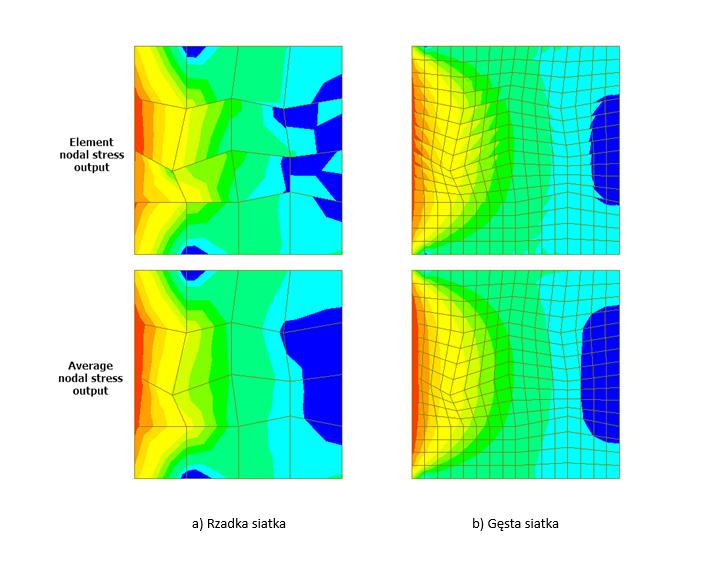
In engineering simulation, CAE simulation accuracy depends on far more than mesh quality alone. A clean and refined mesh is often treated as a sign of model quality, but experienced engineers know that even a beautiful mesh can still produce misleading results.. Smooth element transitions, low skewness, good aspect ratios, and fine local refinements can certainly improve numerical stability. However, experienced CAE engineers know an uncomfortable truth:
A beautiful mesh does not guarantee accurate simulation results.
In fact, some of the most misleading CAE results come from models that look technically “perfect” at first glance. Stress plots appear smooth, deformation contours look realistic, and the solver converges without warnings—yet the engineering conclusion is completely wrong.
At TAS US, we frequently see cases where teams spend significant time optimizing mesh quality while overlooking more critical modeling assumptions. The result is often costly design decisions based on simulations that do not reflect physical reality.
Mesh Is Only One Part of CAE Simulation Accuracy
Mesh quality matters, but CAE accuracy depends on the entire physical model—not just discretization.
Four core factors determine whether a simulation is trustworthy:
- Geometry representation
- Loading conditions
- Boundary conditions
- Material behavior
If any of these are incorrect, even the best mesh cannot rescue the analysis.
Below are seven common reasons CAE simulations produce misleading results despite having excellent mesh quality.
1. Incorrect Boundary Conditions
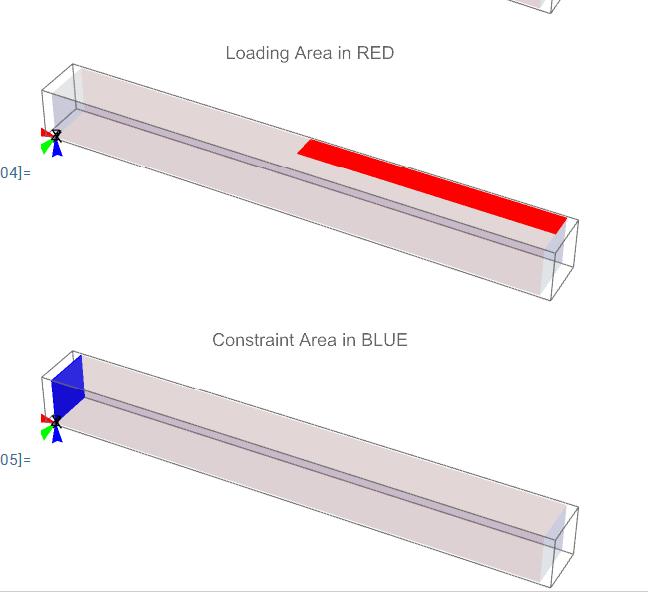
Boundary conditions are among the most common sources of simulation error.
Improperly defined constraints—such as fixed supports, pinned joints, symmetry constraints, or rigid connections—can dramatically alter load paths and stiffness distribution.
For example, fully fixing a component that in reality has compliance or rotational freedom may artificially increase stiffness and reduce displacement. On the other hand, under-constraining a model can introduce rigid body motion or unrealistic deformation.
A mesh may accurately solve the mathematics, but if the constraints do not reflect real-world support conditions, the result is physically meaningless.
Ask this question before trusting any result:
Does the model behave the same way as the real system would under constraint?
2. Unrealistic Loading Conditions
Even perfectly meshed models fail when loads are incorrectly applied.
Common mistakes include:
- Applying force at the wrong location
- Using incorrect load direction
- Misrepresenting pressure distribution
- Ignoring transient or cyclic loading behavior
- Applying overly simplified thermal profiles
Consider a bracket subjected to distributed contact pressure in reality, but modeled with a concentrated point force. The stress field may show dramatic peaks that never occur in physical testing.
The simulation may look “clean,” but the physics is wrong.
Beautiful results built on unrealistic loads are simply polished mistakes.
3. Incorrect Material Properties or Missing Nonlinearity
Material definition is another critical source of error.
Engineers often input only linear elastic properties:
- Young’s modulus (E)
- Poisson’s ratio (ν)
But real engineering materials often exhibit nonlinear behavior such as:
- Plastic deformation
- Creep
- Viscoelastic response
- Hyperelastic behavior
- Strain-rate dependency
If yield stress, plastic hardening curves, or nonlinear constitutive behavior are omitted, stress and deformation predictions can deviate significantly from reality.
For polymers, elastomers, rubber components, seals, and high-temperature applications, this becomes especially critical.
No amount of mesh refinement can compensate for incorrect material physics.
4. Improper Contact Definitions
Contact modeling is one of the most difficult aspects of CAE.
Incorrect contact settings frequently produce false local stresses or unrealistic global stiffness.
Typical issues include misuse of:
- Bonded contact
- Frictional contact
- No-separation contact
- Contact stiffness parameters
- Penalty formulation settings
For instance, modeling two sliding surfaces as fully bonded eliminates relative motion and may make the assembly unrealistically stiff.
Similarly, poor contact stiffness settings may generate artificial stress concentrations near interfaces.
When contact physics are wrong, simulation results can become highly deceptive.
This is especially important in assemblies involving:
- Bolted joints
- Press-fit components
- Weld interfaces
- Multi-body mechanical systems
5. Wrong Element Type or Poor Element Strategy
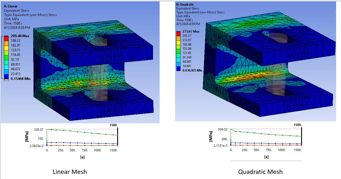
Many engineers assume finer mesh automatically means higher accuracy.
That assumption is dangerous.
Element type matters just as much as element density.
Choosing between:
- Linear vs quadratic elements
- Shell vs solid elements
- Hex vs tetra elements
- Reduced vs full integration
can drastically affect results.
A fine tetra mesh using unsuitable elements may still underperform compared with a well-designed structured mesh.
Good CAE practice is not about generating the most refined mesh possible.
It is about selecting the right element formulation for the physics involved.
Mesh strategy must serve the problem—not aesthetics.
6. Ignoring Geometric or Material Nonlinearity
Linear analysis is fast and convenient, but many real-world engineering problems are nonlinear by nature.
Linear assumptions fail when dealing with:
- Large deformation
- Buckling or instability
- Strong contact interactions
- Plastic yielding
- Large rotations
A structure may appear safe under linear analysis while actually failing due to nonlinear instability.
Buckling analysis is a classic example. A linear static model may predict acceptable stress levels, yet completely miss catastrophic instability behavior.
If the problem contains nonlinear physics, linear simulation can produce fundamentally wrong conclusions.
7. Results Have Not Truly Converged
Convergence is often misunderstood.
Solver convergence does not automatically mean engineering convergence.
A simulation may complete successfully while critical output values remain unstable.
Important outputs to monitor include:
- Maximum stress
- Contact pressure
- Plastic strain
- Reaction forces
- Energy balance
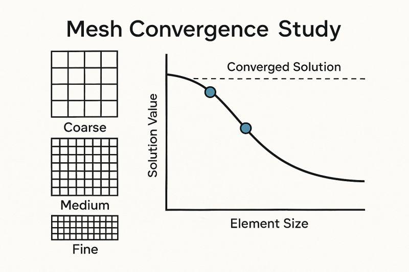
Engineers should perform convergence studies by refining mesh or solver settings and observing whether critical outputs stabilize.
Without convergence validation, a visually impressive mesh can still lead to incorrect decisions.
Warning Signs of Poor CAE Simulation Accuracy
Even without physical testing, several warning signs indicate simulation problems.
Be cautious when you observe:
Unrealistic stress concentrations
Sudden stress spikes at sharp edges, constraints, or contact zones may indicate modeling artifacts rather than real failure.
Unbalanced reaction forces
Reaction force mismatch often signals incorrect boundary conditions or load application.
Unrealistic deformation
If displacement patterns contradict engineering intuition, something may be wrong.
Excessive sensitivity
Small parameter changes causing large output variation may indicate unstable modeling assumptions.
Poor correlation with physical testing
When simulation consistently disagrees with lab or field results, model assumptions must be reviewed.
Experienced CAE engineers do not trust contour plots alone—they validate physical behavior.
How to Improve CAE Simulation Accuracy Before Design Decisions
Before using CAE results for design decisions, perform a structured verification checklist.
At TAS US, our CAE validation workflow typically includes:
Unit consistency check
Verify geometry, load, stress, and material units.
Boundary condition review
Confirm support and constraint assumptions match physical reality.
Contact validation
Check contact pair behavior, friction assumptions, and penetration behavior.
Material verification
Ensure all linear and nonlinear material properties are correct.
Convergence study
Verify key output metrics stabilize with refinement.
Analytical or experimental correlation
Compare results with hand calculations, theory, or physical tests whenever possible.
These validation steps dramatically improve simulation confidence.
CAE Is Physics Modeling—Not a Mesh Beauty Contest
One of the biggest misconceptions in engineering simulation is equating mesh quality with simulation quality.
Mesh quality is necessary—but insufficient.
The true objective of CAE is not producing attractive contour plots.
The objective is enabling reliable engineering decisions.
At TAS US, our CAE workflow focuses not only on solver execution, but on building physically accurate simulation models that engineers can trust for design validation, optimization, and risk reduction.
Because in real engineering, a wrong simulation can be more dangerous than no simulation at all.
A beautiful mesh is a necessary condition—not a sufficient one.
CAE results are trustworthy only when the model accurately reflects real physics.
If loads, boundary conditions, or material behavior are wrong, a better mesh only makes the mistake harder to detect.
The goal of CAE is not creating visually impressive models—it is generating results that support sound engineering decisions.
To learn more about the FEA platform, you can also consult resources from the ANSYS Learning Forum or SIMULIA Documentation.
Need Reliable CAE Simulation Support?
TAS US provides advanced CAE engineering services for manufacturers seeking accurate simulation-driven design decisions, including structural analysis, nonlinear FEA, crash simulation, thermal analysis, and design optimization.
Whether you need early-stage design validation or advanced multiphysics simulation, our engineering team helps transform complex physical behavior into actionable engineering insight.
No responses yet